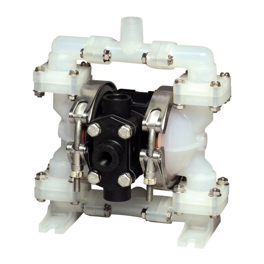
Alemite 8301 Руководство по эксплуатации - Страница 5
Просмотреть онлайн или скачать pdf Руководство по эксплуатации для Водяной насос Alemite 8301. Alemite 8301 11 страниц. Air-operated double diaphragm pump
Также для Alemite 8301: Руководство по обслуживанию и эксплуатации (10 страниц)

NOTE: When the valve cage is properly seated, it will
be about flush with the top of the outlet cavity.
5. Replace the top "O" ring (16) in the outlet cavity.
6. Replace the outlet manifold (13) and replace the
four nuts (4), lockwashers (3) and flatwashers (2) that
hold the outlet manifold to the two end castings (21).
7. Tighten the nuts until firm. Do not over tighten.
COMPLETE PUMP:
(Figure 6)
NOTE: It is not necessary to remove the air-control
valve when completely disassembling the pump.
Disassembly:
1. Remove the outlet manifold and the outlet check-
valve assemblies as described in the disassembly
procedure in the Outlet Check Valve Section.
2. Remove the two bases, the inlet manifold and the
inlet check-valve assemblies as described in the
disassembly procedure in the Inlet Check Valves
Section.
3. Remove the six tie rods (1) from the pump assembly.
4. Slide off each end casting (21) from the center
body.
NOTE: Do not let the studs get bent.
5. Hold one diaphragm retaining nut (20) with a
wrench and unscrew the other one.
6. Pull the diaphragm (46) off the center rod (24).
NOTE: The center disk (22) may be stuck to the
diaphragm.
7. Pull the center disk from the diaphragm.
8. Pull the diaphragm cushion (18) from the center
rod (24).
9. Remove the "O" ring (5) from the body.
10. Repeat steps 6 through 9 for the other side of the
pump.
11. Remove body B (27) from body A (25).
12. Remove the bushing (8) from body B (27) and
remove the "O" ring (7) from the bushing.
page revised 6-03
13. Remove the "O" ring (6) from inside the center
hole in body B.
14. Remove the center rod (24) from body A and
remove the spacer (9) from the center rod.
15. Remove the gasket (26) from body A (25).
16. Remove the bushing (8) from body A (25) and
remove the "O" ring (7) from the bushing.
17. Remove the "O" ring (6) from inside the center
hole in body A (25).
18. Lift out the two springs (10) and the two pilot
guides (11) with the pilot valves (12) attached.
19. Remove the two screens (38) and silencer (39)
from body A (25).
20. Clean and inspect all parts. Replace the silencer
if it cannot be cleaned. If any kits are used, use all
parts in the kit. Replace any other parts that are worn
or show signs of disintegration due to the corrosive
effects of some of the fluids.
NOTE: This procedure does not include the
disassembly of the air-valve as described in the Air-
Valve Section, as these parts do not have to be
removed in order to disassemble the rest of the
pump. If the air-valve needs to be serviced, see that
section of the service sheet.
Reassembly:
1. Install the two screens (38) and the silencer (39)
into body A (25).
2. Reinsert the two springs (10) and the two pilot
guides (11) with the pilot valves (12) attached into the
holes in body A (25).
3. Replace the gasket (26) on body A (25).
NOTE: Be sure to turn the gasket so that the dimples
are facing down and are into the air-valve slots. Align
the gasket on the two metal pins on body A (25).
NOTE: Before reinstalling the two bushings each with
the two "O" rings (6 & 7), apply a little general-
purpose grease to the "O" rings.
4. Insert one "O" ring (6) into the center hole in body
A (25).
5. Insert one "O" ring (7) into one bushing (8) and
attach that bushing to the spacer (9).
SER 8301
page 5
