Clarke C10 Руководство по применению, установке и обслуживанию продукции - Страница 3
Просмотреть онлайн или скачать pdf Руководство по применению, установке и обслуживанию продукции для Водяной насос Clarke C10. Clarke C10 10 страниц. Electric motor driven fire pumps

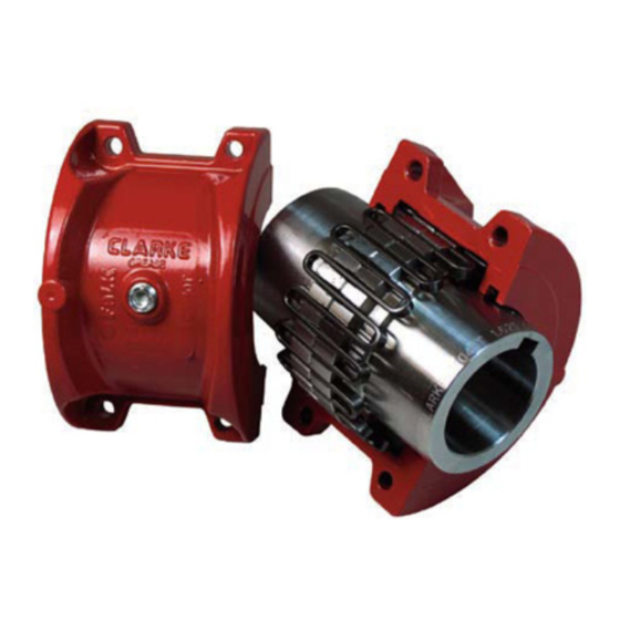
INSTALLATION AND ALIGNMENT OF TYPE C10,
C31 and C35 TAPERED GRID COUPLINGS
Installation
Only standard mechanics tools, wrenches, a straight edge
and feeler gauges are required to install Clarke tapered
grid couplings. Coupling Sizes C1040T thru C1080T are
generally furnished for CLEARANCE FIT with setscrew
over the keyway.
Special applications may call for
Interference fit with or without a setscrew over the
keyway.
CLEARANCE FIT HUBS – Clean all parts using a non-
flammable solvent. Check hubs, shafts and keyways for
burrs. Do not heat clearance fit hubs. Install keys, mount
hubs with flange face flush with shaft ends or as
otherwise specified and tighten setscrews.
INTERFERENCE FIT HUBS – Furnished without
setscrews. Heat hubs to a maximum of 275°F (135°C)
using an oven, torch, induction heater or an oil bath. To
prevent seal damage, DO NOT heat hubs beyond a
maximum temperature of 400°F (205°C). When an oxy-
acetylene or blow torch is used, use an excess acetylene
mixture. Mark hubs near the center of their length in
several places on hub body with a temperature sensitive
crayon, 275°F (135°C) melt temperature. Direct flame
towards hub bore using constant motion to avoid
overheating an area.
WARNING: If an oil bath is used, the oil must have a
flash point of 350°F (177°C) or higher. Do not rest hubs
on the bottom of the container. Do not use an open flame
in a combustible atmosphere or near combustible
materials. Heat hubs as instructed above. Mount hubs as
quickly as possible with hub face flush with shaft end.
Allow hubs to cool before proceeding. Insert setscrews
(if required) and tighten.
Maximize Performance and Life
The performance and life of couplings depend largely
upon how you install and maintain them.
installing couplings, make certain that foundations of
connected
equipment
to
be
requirements. Check for soft foot. The use of stainless
steel shims is recommended. Measuring misalignment
and positioning equipment within alignment tolerances is
simplified with an alignment computer.
calculations
can
also
mathematically. Alignment is shown using spacer bar and
straight edge. This practice has proven to be adequate for
many industrial applications. However, for superior final
alignment, the use of dial indicators, lasers, alignment
computers or graphical analysis is recommended.
CAUTION: Consult applicable local and national safety
codes for proper guarding of rotating members. Observe
all safety rules when installing or servicing couplings.
Before
meet
manufacturers'
These
be
done
graphically
WARNING: Lockout starting switch of prime mover and
remove all external loads from drive before installing or
servicing couplings.
1 – Mount Seals and Hubs
Clean all metal parts using a non-flammable solvent.
Lightly coat seals with grease and place on shafts
BEFORE mounting hubs. If specified, heat interference
fit hubs as previously instructed. Seal keyways to prevent
leakage. Mount hubs on their respective shafts so the hub
face is flush with the end of its shaft unless otherwise
indicated. Tighten setscrews when furnished.
NOTE:
Follow
recommendations for baseplate settings, rough alignment
and baseplate grouting prior to performing the following
final alignment steps, 2 and 3.
2 – Gap and Angular Alignment (x – y)
Use a spacer bar equal in thickness to the gap specified in
Table 2, Page 5. Insert bar as shown, above, to same
depth at 90° intervals and measure clearance between bar
and hub face with feelers. The difference in minimum
and maximum measurements must not exceed the
or
ANGULAR installation limits specified in Table 2.
Page 3 of 10
the
Fire
Pump
Manufacturer's
