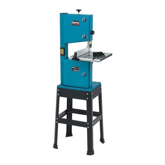
Clarke WOODWORKER CBS250 Инструкции по эксплуатации и техническому обслуживанию - Страница 14
Просмотреть онлайн или скачать pdf Инструкции по эксплуатации и техническому обслуживанию для Пила Clarke WOODWORKER CBS250. Clarke WOODWORKER CBS250 20 страниц. 45 mm (10”) bandsaw & stand
Также для Clarke WOODWORKER CBS250: Руководство по эксплуатации и техническому обслуживанию (13 страниц)

A. Upper Blade Guides
1.
Slacken the grub screw 'A' Fig.17, and move
the rear guide roller so that it comes into light
contact, or to within 0.5mm of the back
edge of the sawblade, as shown at 'D',
Fig17. When satisfied, retighten the grub
screw
2.
Slacken grub screws 'B' and 'C' Fig.17 and
move the side guide rollers so that they come
into light contact, or to within 0.5mm, of the
sawblade. Retighten the grub screws.
NOTE: It is important that the side guides rollers
cover as much of the blade as possible,
WITHOUT coming into contact with the saw
blade teeth, see Fig. 17a.
If the guides require adjusting, proceed as follows:
•
Slacken grub screw
'D' Fig.18 and move
the complete
assembly so that
the guide rollers are
positioned correctly,
as shown in Fig 17a.
When satisfied,
retighten the grub
screw.
B. Lower Blade Guides
1. Slacken the thumb screw, (see Fig. 19), and move the
edge of the rear guide roller so that it comes into light
contact, or to within 0.5mm of the back edge of the
sawblade. When satisfied, retighten the grub screw
2. Slacken the grub screws, (see Fig.20), 'A' & 'B', and move
the side guides so that they come into light contact,
or to within 0.5mm, of the sawblade. Retighten the grub
screws.
NOTE: It is important that the side guides cover as much of
the blade as possible, WITHOUT coming into contact with
the teeth of the saw blade.
If the guides require adjusting, proceed as follows:
•
Slacken the securing nut, at the rear of the guide
assembly, (see Fig.20). Move the assembly as required,
ensuring the guides remain square to the sawblade. When
satisfied they are correctly positioned, tighten the nut,
taking care not to move the guide assembly.
When all guide adjustments are complete, refit the table,
table insert and width of cut indicator.
'D'
Fig.18
14
Fig.17
Upper Blade Guides
'B'
'C'
✘ ✔
0.5mm
MAX
Front View
Front View
Thumb
screw
Rear View
'A'
'D'
'A'
0.5mm
MAX
Fig.17a
Side View
Fig.19
Fig.20
'B'
Securing Nut
