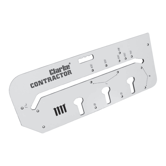
Clarke CONTRACTOR CWJ700 Руководство по эксплуатации и техническому обслуживанию - Страница 7
Просмотреть онлайн или скачать pdf Руководство по эксплуатации и техническому обслуживанию для Инструменты Clarke CONTRACTOR CWJ700. Clarke CONTRACTOR CWJ700 20 страниц. Worktop jig

4. Ensure the 3 pins in holes 'F' are pushed firmly against the post formed edge, and the
fourth pin in the hole marked with the worktop width is pushed firmly against the worktop
edge.
5. Firmly clamp the jig onto the worktop ensuring the clamps do not obstruct the router
path.
6. Cutting-Position the router (guide bush) in the jig slot at the post form end, ensure the
router base is flush on the jig surface. Set the cut depth to 10mm max.
7. IMPORTANT: Ensure the router is pulled towards the slot edge nearest you (Face 'A'
Fig.4). Switch the router ON and slowly move it, held firmly against face A, until the
far end of the workpiece is reached. Switch OFF and wait for the cutter to stop
spinning.
8. Lift the router out off the slot and return it to the start position again, increase the
depth of cut a further 10mm and make a second pass. Keep repeating steps 7 & 8
until the cut is complete, i.e. the cutter is below the bottom of the worktop.
9. Switch the router OFF and wait for it to stop spinning, return the router to the start
position again. Switch ON, this time, push the router against the slot edge furthest
from you (Face 'B', Fig.4) and make one finishing cut AT FULL DEPTH. When finished,
switch OFF and wait for the cutter to stop spinning, remove the router and jig, store
them away safely for reuse.
Male Joint (Fig. 5)
10.
to protect the surface.
11. Fully insert two pins in the jig holes marked 'M' with angle symbol
12. Refer to page 10, (cutting to length) to determine where to mark the pencil line for
positioning the jig on the worktop.
13. Ensure the two pins in holes 'M' are pushed firmly against the post form edge and
the jig lined up on the pencil line as above (Fig. 5).
14. Firmly clamp the jig to the worktop ensuring it doesn't move as you do so. Ensure the
clamps do not obstruct the router path.
Cutting
15.
- follow steps 6 - 9 above.
- Place the worktop with the laminate face down, taking care
Pencil Line
Male Joint - Laminate face down.
Fig. 5
.
Cut Direction
Post Form Edge
-6-
