CLAS OM 9381 Руководство - Страница 9
Просмотреть онлайн или скачать pdf Руководство для Инструменты CLAS OM 9381. CLAS OM 9381 12 страниц. Hgv silent-block puller/installation set

OM 9381
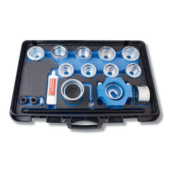
HGV SILENT-BLOCK PULLER/INSTALLATION SET
Pre-tensioned spring bushing assembly
Route the thrust screw through the support where the new bushing is to be inserted (for example, leaf spring hole)
until it protrudes slightly from the other end.
Note: before each use, lubricate the thrust screw with the grease provided.
2. Choose a support socket of the suitable size, place it on the step plate and then on the thrust screw, at the back.
Place the socket so that you can clearly see the inspection window.
Note: when choosing the socket, make sure that any foreseen projection in the bushing to be inserted will pass
through the support socket's inside diameter. In addition, you should have a support surface adequate yo the
support socket on the vehicle's component.
3. Now push the pre-tensioned bushing with the screw until it has fully entered the leaf spring hole. Make sure the
bushing's position is the same as the original one.
4. Place the presser, suitable to the chosen semirings kit, behind the bushing to be inserted on the thrust screw. The
presser's open side should face the bushing to be inserted.
Note: the presser should press against the bushing's outer metal coating. The presser is made so that it has the
same internal size as the clamp. This means that when the presser has fully entered inside the clamp, the bushing
will be aligned precisely inside the seat.
5. Place the thrust nut behind the step plate on the thrust screw. Tighten the thrust nut until it protrudes from the thrust
screw by about 2 cm. Act on the thrust nut and at the same time act on the second thrust nut to pull out the bushing
to be removed and placed inside the support socket.
Warning: during assembly, always check the correct position of all components, correcting it when necessary.
Note: in view of the forces required, at times enormous, especially during removal, we suggest the use of a
hydraulic cylinder. The hydraulic cylinder OH 3512 can be used.
Assembly option with hollow piston hydraulic cylinder
At rst, follow steps 1 to 4 described in the Pre-tensioning point and then steps 1 to 5 in the pre-tensioned bushing
assembly point.
Push the hydraulic cylinder with its at side on the thrust screw. The thread faces the opposite direction towards the
bushing to be inserted.
Place the U-shaped disc and the thrust nut behind the hydraulic cylinder on the spindle and tighten the nut by hand.
Connect the hydraulic pump to the cylinder, actuate it and then insert the bushing into the leaf spring hole by taking
it out from the clamp lock.
Note: the U-shaped spacer included in the supply is required as a lifting extension when used with a hydraulic
cylinder.
