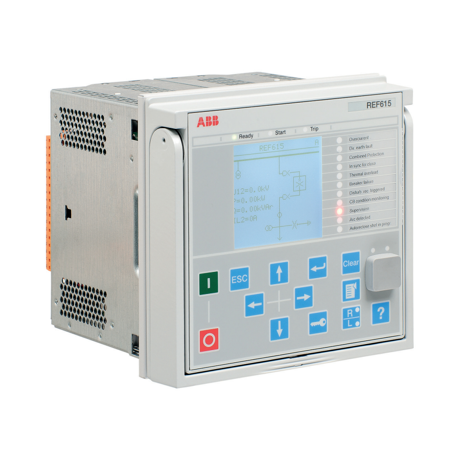
ABB REM615 ANSI Руководство по применению - Страница 19
Просмотреть онлайн или скачать pdf Руководство по применению для Устройство защиты ABB REM615 ANSI. ABB REM615 ANSI 20 страниц. Motor protection and control

1YHT530017D05 B
REM615
Application Manual
Table 2:
Plug-in unit and case
Main unit Slot ID
Content options
Plug-in
-
HMI
unit
X100
Auxiliary power/BO
module
X110
BIO module
X120
AI/BI module
AI/BI module
Case
X130
AI/BI module
Optional RTD/mA module
Optional BIO module
X000
Optional communication
module
1) BIO module (X110) is optional for configuration A.
2) The 0.2/1A input is normally used in applications requiring sensitive earth-fault protection and
featuring core-balance current transformers.
Rated values of the current and voltage inputs are basic setting parameters of the
IED. The binary input thresholds are selectable within the range 18...176 V DC by
adjusting the binary input setting parameters.
The connection diagrams of different hardware modules are presented in this manual.
See the installation manual for more information about the case and
the plug-in unit.
Small (4 lines, 16 characters)
Large (8 lines, 16 characters)
48-250 V DC/100-240 V AC; or 24-60 V DC
2 normally-open PO contacts
1 change-over SO contact
1 normally-open SO contact
2 double-pole PO contacts with TCS
1 dedicated internal fault output contact
8 binary inputs
1)
4 signal output contacts
3 phase current inputs (1/5A)
1 residual current input (1/5A or 0.2/1A)
4 binary inputs
Only with configuration B:
3 phase current inputs (1/5 A)
1 residual current input (1/5 A or 0.2/1 A)
3 phase voltage inputs (60-210 V)
Only with configuration C and J:
3 phase voltage inputs (60-210 V)
1 residual voltage input (60-210 V)
4 binary inputs
Optional for configurations A and B:
2 generic mA inputs
6 RTD sensor inputs
Optional for configuration B:
6 binary inputs
3 signal output contacts
See the technical manual for details about different
types of communication modules.
Section 2
REM615 overview
2)
13
