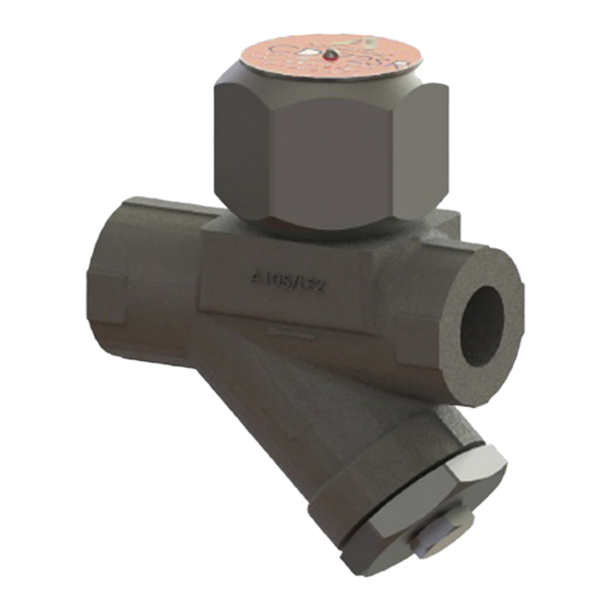
Armstrong CD72SR Руководство по установке и эксплуатации - Страница 3
Просмотреть онлайн или скачать pdf Руководство по установке и эксплуатации для Блок управления Armstrong CD72SR. Armstrong CD72SR 11 страниц. Control disc steam trap

General Safety Information
This document should be used by an experienced person as a guide for installing the Armstrong
CD72SR Control Disc Steam Trap. Selection or installation of equipment should always be
accompanied by competent technical assistance. You are encouraged to contact Armstrong
International Inc., or its local sales representative for additional information.
Product Information
Armstrong CD72SR is a disc styled trap designed to control the trap's cycle rate. The reduced
cycle rate provides Armstrong CD72SR trap with a longer service life than typical disc traps. This
enhanced performance ensures minimum maintenance time and reduced steam costs.
The capacity of Armstrong CD72SR has been engineered specifically for the following
applications: large steam main drips, process equipments and HVAC heating equipments at
constant pressure.
Armstrong CD72SR is available in socket weld and screwed connections (flanged connections
on request) for the maximum operating pressure range of 600psig@ 486°F (41.4 barg @ 252°C)
and in 1/2", 3/4" and 1" (DN15, DN20, DN25) sizes.
Note:
•
Minimum pressure for satisfactory operation is 5 psig (0.34 barg).
•
Maximum back pressure should not exceed 80% of the inlet pressure. If back pressure
exceeds 80% of inlet pressure, the trap may not shut. At 50% to 70% back pressure traps
may become unstable. Therefore, Armstrong suggests limiting back pressure to 50% of inlet
pressure.
Product Installation
1. Before installing the trap, blow down the piping that leads to the trap's inlet. Use full line
pressure. Be sure that the maximum operating pressure (PMO) of the trap is adequate for the
installation. (The PMO is stamped on the nameplate).
2. Install the trap inlet below the liquid level of the equipment to be drained. Make inlet piping as
short as possible. Use a minimum number of elbows and other restrictions in inlet and outlet
piping. Install a dirt pocket in the line ahead of the trap.
3. To allow for maintenance, install a valve on each side of the trap and a downstream testing
tee (unless test valve is used as the downstream valve). All valves should be full ported type to
avoid restricting flow.
4. If possible, install the trap in the horizontal position. For freeze-resistant applications, inlet
piping must be pitched towards the pipe for gravity flow. Additionally, the trap must be installed
vertically, discharging downward. Discharge piping must be self-draining.
Designs, materials, weights and performance ratings are approximate and subject to change without notice. Visit armstronginternational.com for up-to-date information.
North America • Latin America • India • Europe / Middle East / Africa • China • Pacific Rim
armstronginternational.com
1
