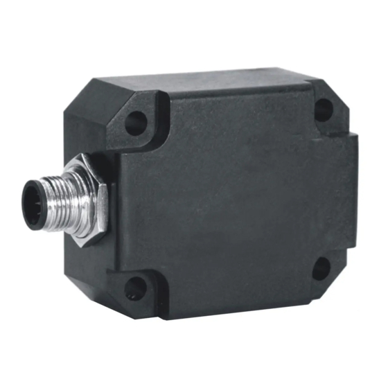
DIS Sensors CAN Руководство пользователя - Страница 4
Просмотреть онлайн или скачать pdf Руководство пользователя для Аксессуары DIS Sensors CAN. DIS Sensors CAN 18 страниц. Inclination safety sensor

CAN User Manual
Inclination Safety Sensor
(Type D) V2.0
3
Safety, Installation, use & maintenance
• By ignoring the safety instructions the manufacturer cannot be hold responsible for any damage or
hazard.
• If any damage is noticed (M12 connector(s) and/or the enclosure) the device must be replaced by a new
one in order to avoid hazard.
• Never move the sensor by pulling the cable.
• The device should only be used in situations covered by the datasheet.
• Only a SELV power supply should be used.
• Only the CANopen Safety interface according to EN50325-5 should be used.
• As this device is accelerometer-based the sensor is inherent sensitive for accelerations/vibrations.
Application specific testing must be carried out to check whether this sensor will fulfil customer
requirements.
• The family of sensors involved will have a variety of types due to different outputs, measuring ranges,
enclosures and connection options. Datasheets are available for each specific type. Customer must select
and read the datasheet for the product he is using.
• The Safety Related Fault Response Time (SRFRT) of this device is defined as the maximum time the sensor
will report a non-safe situation to the outside world, after detecting an internal safety error. Actual value
is specified in the datasheet
• Configuration of the device like changing Node-ID, COB-ID's and centring (sensor-offset) can only be done
after a new CRC-code is generated separately and written to the device.
• The sensor should be mounted on a stable flat surface with all screws tightened.
• Use only double twisted double shielded CAN cables.
• The proof test interval for this sensor is 20 years. After this interval the sensor should be replaced or
checked by comparing the output to a reference sensor or checked / recalibrated by the manufacturer.
This is to check for any non-detectable faults and/or degradation. This check / recalibration is not included
in the price.
• The calculated MTTFd of the sensor is specified in the datasheet.
• This sensor does not require any maintenance between proof-test intervals.
The user of this safety device shall only use this device when:
• he is educated to design in / use functional safety sensors.
• he has taken knowledge of both the datasheet and the user manual.
• the zeroing / centering function is only performed in the right position by an authorized person.
• the redundancy compare parameters (both Redundancy Compare Time and Redundancy Compare Angle)
are set by the customer according to the application demands. The actual values used by the customer
should fit the application involved. Before using this sensor and with the settings chosen the customer
should evaluate risks in order to check whether the chosen settings satisfy his safety requirements.
Manufacturer is not responsible for any damage caused by these customer-setting, even when the
manufacturer defaults are used.
• the bandwidth settings are according to the application demand
• the device is used inside the specified environmental situation
The user of this safety device shall consider its output as 'defective' in the following situations:
• the device is not responding
• the device is not running in operational state
• the device is not running in the desired mode of operation. To be checked at installation/start-up.
• the device is sending an emergency message
• the device switches to NMT stop state
• the safeguard cycle time (SCT) exceeds the limit
• the safety related validation time (SRVT) exceeds the limit
• the angle output is 200°
Page 4 of 18
