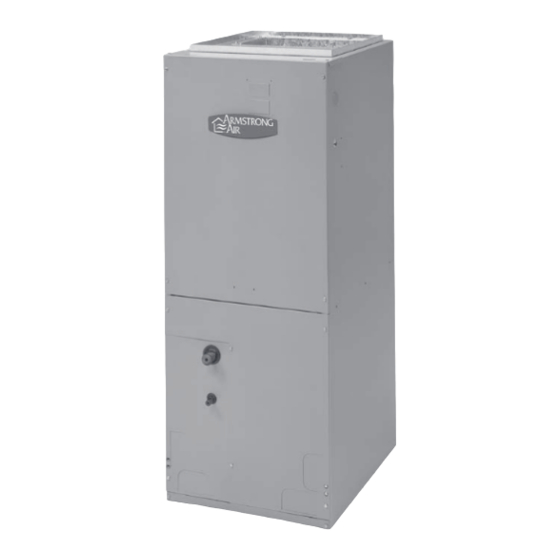
Armstrong Air BCS2 Series Руководство по установке - Страница 3
Просмотреть онлайн или скачать pdf Руководство по установке для Воздухораспределители Armstrong Air BCS2 Series. Armstrong Air BCS2 Series 15 страниц.

If installed in an unconditioned space, sealant should be
•
applied around the electrical wires, refrigerant tubing,
and condensate lines where they enter the cabinet.
•
Electrical wires should be sealed on the inside where
they exit the conduit opening. Sealant is required to
prevent air leakage into and condensate from forming
inside the air handler, control box, and on electrical
controls.
The air handler must be installed in such a way as to
•
allow free access to the coil/filter compartment and
blower/control compartment.
The air handler must be installed with a ¾" drop in the
•
horizontal position towards the drain pan to ensure
proper condensate drainage.
IMPORTANT
The Clean Air Act of 1990 bans the
intentional venting of refrigerant (CFC's and
HFC's) as of July 1, 1992. Approved
methods of reclaiming must be followed.
Fines and/or incarceration may be levied for
non compliance.
Installation Clearances
Non-Ducted Return Closet Installation
The air handler can be installed in a closet with a false bottom to
form a return air plenum or be installed with a return air plenum
under the air handler.
Louvers or return air grilles are field supplied. Local codes may
limit application of systems without a ducted return to single-story
buildings.
•
For a unit installed in a closet with a louvered return
opening, the minimum open area for the louvers will be
320 square inches for 18 and 24 models
-
360 square inches for 30 and 36 models
-
450 square inches for 42, 48 and 60 models
-
If the free area is not known, assume a 25% free area
•
for wood or a 75% free area for metal louvers or grilles.
Using the louver dimensions and the 25% or 75%
assumption, determine if the louver open area meets
the minimum open area listed above.
•
If the return air plenum is used, the return air grille
should be immediately in front of the opening in the
plenum to allow for the free flow of return air.
When not installed in front of the opening, there must be
•
adequate clearance around the air handler to allow for
the free flow of return air.
Installation Configurations
3
For ease in installation, it is best to make any necessary coil
configuration changes before setting air handler in place. See
"Installation Configuration Options."
Upflow air discharge only contains 1 drain pan.
•
Upflow or horizontal airflow contains 2 drain pans.
•
Vertical Installations
Upflow
The air handler must be supported on the bottom only and set on
solid floor or field supplied supporting frame. Securely attach the
air handler to the floor or supporting frame.
Horizontal Installations
Horizontal installations can be left-hand or right-hand air supply.
Adequate support must be provided to ensure cabinet integrity.
Ensure that there is adequate room to remove service and
access panels if installing in the horizontal position. For correct
horizontal coil installation, see "Installation Configuration
Options."
IMPORTANT:
This coil is provided with a secondary drain that should
•
be trapped and piped to a location that will give the
occupant a visual warning that the primary drain is
clogged. See "Install Condensate Drain."
When an evaporator coil is installed in an attic or above
•
a finished ceiling, an auxiliary drain pan should be
provided under the air handler as specified by most
local building codes.
Conversion from Vertical to Horizontal
An upflow only air handler may be converted to horizontal air
discharge by installing a horizontal drain pan kit. See
"Accessories."
An upflow/horizontal air handler may be converted from
horizontal left-hand discharge to horizontal right-hand discharge
without additional parts.
Suspended Cabinet Installation
NOTE:
Air handlers cannot be installed horizontally lying on or
suspended from either the front or back of the air handler. It must
be positioned with one side parallel to the floor when in the
horizontal position.
The suspending means must be field fabricated, and should
consist of 2 "cradles" made by attaching 2 rods to a length of
angle iron or suitable gauge steel.
