ARMTEL ARMT.665200.104UM Руководство пользователя - Страница 9
Просмотреть онлайн или скачать pdf Руководство пользователя для Блок управления ARMTEL ARMT.665200.104UM. ARMTEL ARMT.665200.104UM 20 страниц. 8 fuse module

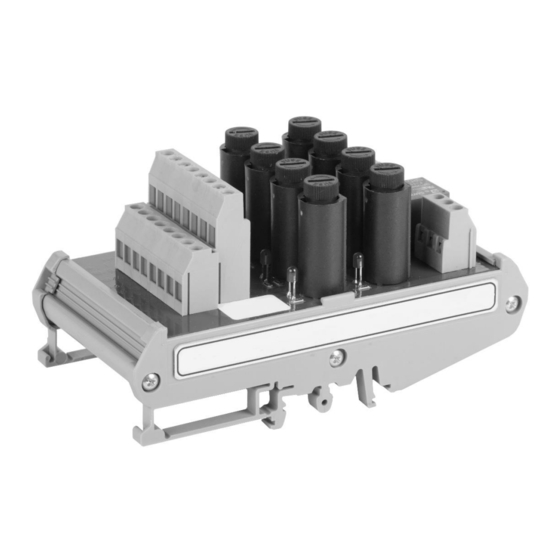
1 – contacts for 1-16 Х1 terminal block for power lines of subscriber equipment; 2 – VD1-VD8 –
LEDs (RED) for indication of the blown fuses F1 – F8. Solid lighting for identification of the blown fuse;
3 – F1- F8 – Holders with fuses; 4 –Х2 Terminal block, its contact are closed with K1 relay contacts in
case of fuse malfunction. It can be used for alarm signaling using an external executive device
(a lamp, a siren, etc.). The switching voltage is up to 250VAC, the switching current is up to 7А;
5 –Х3 Terminal block, duplicates the contacts of X2 terminal block to connect several 8 fuse modules
in parallel, to connect to the common signal even if one/several fuse(s) is/are blown;
6 –Х4 terminal block to connect the power supply source
Figure 1 – External appearance and overall dimensions of 8 Fuse module
The power voltage for the communication systems DCN, IPN is connected to X4
terminal block «POWER INPUT», the power lines of the subscriber equipment are connected
to the contacts of X1 terminal block. To set up the single failure alarm system, the signaling
cables from X2 terminal blocks for the backup 8 modules applied in the communication
system are connected to X3 terminal block.
8 Fuse module can perform the following functions within the digital intercom DCN
and IPN communication systems manufactured by Armtel:
Transmission of the input power voltage of 48V DC from X4 terminal block
«POWER INPUT» to the power lines connected to Х1.1-Х1.4 terminal blocks;
armtel.com
MODULE
8 FUSE
User Manual
ENG
page 7/16
© Armtel
