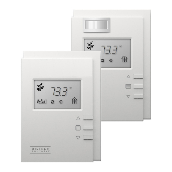
Distech Controls Allure ECL-600 Series Руководство по установке - Страница 5
Просмотреть онлайн или скачать pdf Руководство по установке для Аксессуары Distech Controls Allure ECL-600 Series. Distech Controls Allure ECL-600 Series 17 страниц. Extension modules
Также для Distech Controls Allure ECL-600 Series: Руководство по установке (16 страниц)

Power Wiring
Voltage for UUKL models: 24VAC; ± 15%, Class 2
Voltage for all non-UUKL models: 24VAC/DC; ± 15%, Class 2
This is a Class 2 Product. Use a Class 2 transformer only (rated at 100VA or less at 24VAC) to power the
controller(s).
The Network Guide provides extensive information and requirements for powering a controller. It can be downloaded from our website. For the UUKL ex-
tension module, refer to the Distech Controls UUKL Smoke Control System Design Guide.
It is recommended to wire only one controller per 24VAC transformer.
If only one 24VAC transformer is available, determine the maximum number of controllers that can be supplied using the following method to determine
the required power transformer capacity:
£
Add up the maximum power consumption of all controllers including external loads and multiply this sum by 1.3.
£
If the resulting number is higher than 100VA, use multiple transformers.
Use an external fuse on the 24VAC side (secondary side) of the transformer, as shown below, to protect all controllers against power line spikes.
Maintain consistent polarity when connecting controllers and devices to the transformer. One terminal on the secondary side of the transformer must be
connected to the building's ground. All 24V COM terminals of all controllers and peripherals throughout the LAN or the Subnetwork network must be con-
nected to the grounded transformer terminal as shown below. This ensures that the 24V COM terminals of all devices connected to any LAN or Subnet-
work in the building are at the same potential.
A mechanical ground is unacceptable: Do not use a pipe, conduit, or duct work for a ground. The power supply must
have a dedicated ground wire that comes from the main electrical supply panel.
Failure to maintain consistent polarity throughout the entire network will result in a short circuit and/or damage to the
controller!
The COM terminals of the controller are internally wired to the 24V COM terminal of the power supply. Connecting a
peripheral or another controller to the same transformer without maintaining polarity between these devices will
cause a short circuit.
Fuse: 4 A Max.
Controller 1
Fast Acting
24V AC
24V COM
Controller 2
24V AC
24V COM
Figure 5:
Fuse: 4 A Max.
Controller 1
Fast Acting
24V AC/DC
24V COM
Controller 2
24V AC/DC
24V COM
Figure 6:
Power wiring – DC (for all non-UUKL model only)
24 VAC
AC
Transformer
Electrical System Ground
- At Transformer Only
Power wiring – AC
24 VDC
Electrical System Ground
- At Power Supply Only
5 / 16
