Balmar ARS-5 Руководство по установке и эксплуатации - Страница 7
Просмотреть онлайн или скачать pdf Руководство по установке и эксплуатации для Контроллер Balmar ARS-5. Balmar ARS-5 16 страниц. Multi-stage voltage regulator
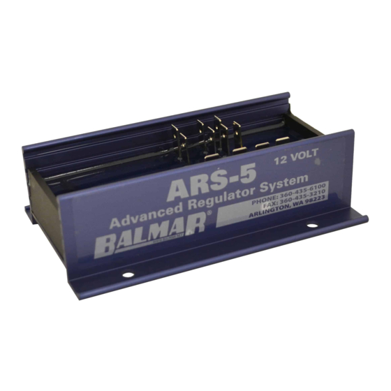
Также для Balmar ARS-5: Руководство по установке и эксплуатации (20 страниц), Краткое руководство по эксплуатации (2 страниц)
Regulator Display Modes
The regulator's three digit alphanumeric LED display provides a scrolling view of charging status. Under normal operation,
the display will indicate the following:
B A L
Indicates Balmar.
A - 5
Indicates Model ARS-5
U F P
Indicates regulator's default Universal Factory Program. Display will vary based on program selected.
b - 0
Indicates the regulator's Belt Load Manager setting. Ranges from b-0 to b-9.
- b -
Indicates stage of charge. "b" indicates bulk. "A" indicates absorption. "F" indicates float.
b v
Indicates system Battery Voltage. Followed by actual voltage reading.
C v
Indicates Calculated voltage (target voltage based on preset program levels). Followed by voltage reading.
B 1
Indicates Battery temperature. Followed by NC (not connected), or temperature in celsius.
A L
Indicates Alternator temperature. Followed by NC (not connected), or temperature in celsius.
In addition to the information provided in the basic display shown above, the ARS-5 long display provides the following
data. The long display is accessed during basic programming, which will be discussed in the next section of the manual.
F E
Indicates the percentage of field output to the alternator. The higher the percentage, the greater the output.
r 3. 8
Indicates regulator's software revision code.
S P
Indicates regulator circuit board temperature. Followed by degrees celsius.
S L P
Indicates, in millivolts per degree C per cell, voltage compensation for battery temperature.
H r
Indicates overall regulator hours. Followed by hours (by tenths) and hours in excess of 100.
F b A
Indicates field threshold; bulk to absorption to float. Factory set at 65%. Adjust in Advanced Programming.
F F L
Indicates field threshold from float to absorption. Factory set at 65%. Adjust in Advanced Programming.
E
Indicates system advisory codes. Individually numbered codes are defined below.
The following advisory codes can be used to determine possible system errors or to identify specific operational modes.
Note that E codes are cumulative and will be held in memory until cleared. Codes can be cleared by entering dSP and
letting it save. Display settings DO NOT need to be changed. See basic programming for more info.
E 1 0
BATTERY TEMP. SENSOR CABLE
SHORTED
E 1 1
BATTERY TEMP. SENSOR CABLE
OPEN OR NOT FOUND
ALTERNATOR TEMP. SENSOR
E 1 4
CABLE SHORTED
E 1 5
ALTERNATOR TEMP. SENSOR
CABLE OPEN OR NOT FOUND
E 2 0
BATTERY EXCEEDS 55˚C.
FACTORY DEFAULT
Short Display/Long Display
-
E 2 2
ALTERNATOR TEMPERATURE
EXCEEDS 107˚C
E 2 4
VOLTAGE REGULATOR
EXCEEDS 90˚C
E 3 0
BATTERY VOLTAGE BELOW
12.5 VOLTS
E 3 4
BATTERY VOLTAGE BELOW
10.5 VOLTS
E 3 5
BATTERY TEMP EXCEEDS
USER ADJUSTED VALUE
- 7 -
E 4 0
BATTERY VOLTAGE
EXCEEDS 16 VOLTS
E 4 1
FIELD VOLTAGE TOO HIGH.
E 4 2
STATOR VOLTAGE TOO HIGH.
E 5 1
SMALL ENGINE MODE IS IN
OPERATION
E 5 2
BELT LOAD MANAGER IS IN
OPERATION