Balmar 94LY Series Руководство по установке и эксплуатации - Страница 13
Просмотреть онлайн или скачать pdf Руководство по установке и эксплуатации для Портативный генератор Balmar 94LY Series. Balmar 94LY Series 20 страниц. Alternator
AT-SERIES ALTERNATORS – 220A
Advanced Technology (AT-Series) alternators are available in three mounting con-
figurations:
•
SF models: 2" single foot.
•
DF models: 3.15" ID saddle mount.
•
DF4 models: 4" (J-180) saddle mount.
•
AT-Series alternators are isolated ground, externally regulated, and
feature 16 stator poles. Field and stator terminals are included in a
pigtail included with the alternator. Terminal connections are as fol-
lows:
1. Positive Output Terminal - Must be connected via properly-
sized cable to the battery or batteries being charged. Cable size is
determined by alternator output and length of cable run. See Page 3
for wiring size chart.
2. Stator Output Wire (WHITE) - Provides an unrectified source of AC
voltage which can be used as a signal for an electric tachometer.
3. External Field Wire (BLUE) - Connects to external voltage regulator
via wiring harness.
4. Negative Output Post (Ground) - Must be connected to system
ground via properly sized cable. Cable size is determined by
alternator output and length of cable run. See Page 3 for wiring size
chart. Ensure that the ground cable is adequately supported to supply
strain relief.
5. Temp Sensor (Not Shown) - There is a tapped hole on the side of
the rear casing for the (Optional) MC-TS-A sensor. Do not bend the
heat shrink or ring terminal
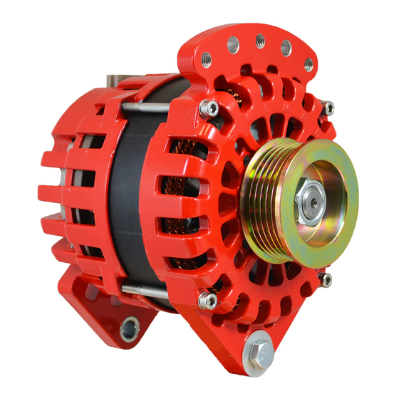
94-SERIES & 94LY-SERIES ALTERNATORS
Large case 94-Series alternators are designed to provide 165 or 210
amps at 12 volts, or 140 amps at 24 volts. Mounting is a 2" single-foot
Delco-style mount for 94-series, and Dual Foot w/3.15 for the 94LY-se-
ries. Alternators in the 94-Series feature isolated ground terminals, exter-
nal regulation and 12-pole stator output.
1. Positive Output Terminal - Must be connected via properly-sized
cable to the battery or batteries being charged. Cable size is deter-
mined by alternator output and length of cable run. See Page 3 for
wiring size chart.
2. Negative Terminal (Ground) - Must be connected to system ground
via properly sized cable. Cable size is determined by alternator output
and length of cable run. See Page 3 for wiring size chart.
3. Stator Output - Unrectified source of AC voltage which can be used
as a signal for an electric tachometer. In 12-volt systems, stator ter-
minal will connect to WHITE wire. In 24-volt systems, the Stator Wire
will connect to the ORANGE wire in the regulator wiring harness.
4. External Field Wire (BLUE) - Connects to external voltage regulator
via wiring harness.
5. Temp Sensor (Not Shown) - There is a tapped hole on the side of the
rear casing for the (Optional) MC-TS-A sensor. Do not bend the heat
shrink or ring terminal
An unsupported cable may damage the positive or negative terminals, resulting
in damage to alternator, regulator and wiring. Ensure that cables are adequately
supported to supply strain relief.
4
2
Page
13
2
1
4
3
1
4
3
3