Cameron TYPE 31 Руководство по установке, эксплуатации и техническому обслуживанию - Страница 5
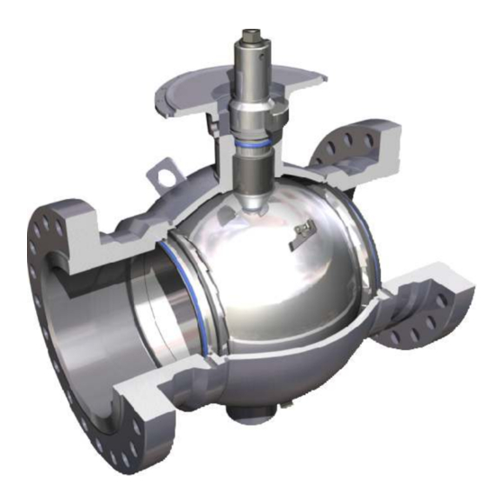
Просмотреть онлайн или скачать pdf Руководство по установке, эксплуатации и техническому обслуживанию для Блок управления Cameron TYPE 31. Cameron TYPE 31 20 страниц. Fully welded body ball valve

Installation
Handling of Valves
1. The valve should be lifted in such a way that
the body supports the load.
CAUTION: The journal and the end connection
necks are suitable places to attach lifting
slings. Never use handwheels or other
protruding parts of the gearbox or actuator
not designated for this purpose.
2. If the valve is equipped with lifting lugs, these
should be used for handling.
3. The end protector covers should be kept in
place on the end connections during all
handling. Remove only during final installation
of the valve.
CAUTION: During handling, protect the end
connection faces and fittings against damage
from the lifting devices. Failure to cover faces
and fittings could cause damage to the valve.
Position of Valve
The ball valve may be installed in any position.
Either end of the valve may be installed as the
upstream end.
Protection of Ball
CAUTION: The ball should be fully open
during the installation of the valve. Failure to
keep the ball fully open during installation
could cause damage to the valve.
If the ball must remain in the closed position
during installation of the valve, coat the
exposed surfaces of the ball with grease.
This will protect the plug from damage due to
weld splatter.
CAUTION: Do not leave the valve in the
partially open position for an extended
period of time.
Installation, Operation and Maintenance Manual
E N G I N E E R E D V A L V E S
Figure 3 - Correct valve lifting using End Connection Necks.
EQUALIZING YOKE
Figure 4 - Correct lifting using the valve Lifting Lugs.
CAUTION: A weld end valve without pup pipes
should never be installed in the closed position.
Welding Instructions
When preheating, welding or stress relieving, body
temperatures must not exceed 400°F (200°C) at
any point beyond 3" (75 mm) from the weld.
Use tempil sticks to check temperatures. Before
CAMERON T31 Fully Welded Body Ball Valves are
welded into final position in the pipeline, cover the
valve seal areas (ball-to-seat area and seat-to-end
connection area) with 1" wide masking tape from
the 3 o'clock to the 9 o'clock position. This will help
prevent any foreign material from becoming lodged
in these areas. The piping system should also be
pigged before operation or pressure testing to
remove any foreign material from the pipeline.
3
IOM-CAM-BALL-T31
