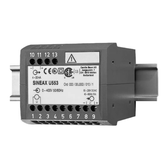
Camille Bauer SINEAX U553 Руководство по эксплуатации - Страница 11
Просмотреть онлайн или скачать pdf Руководство по эксплуатации для Преобразователь Camille Bauer SINEAX U553. Camille Bauer SINEAX U553 12 страниц. Transducer for ac voltage
Также для Camille Bauer SINEAX U553: Руководство по эксплуатации (12 страниц)

6. Adjustable measuring range by DC calibra-
tion
DC calibration is performed at the user's
risk. The warranty is void if the calibration
seal is removed.
Reliably isolate the measuring input from
dangerous voltages.
Setting:
Admissible alteration of full scale
output, variable sensitivity, adjust-
able with potentiometer P200.
Setting range:
0.85 - 1.15 · U
100%
– Remove calibration seal (small sticker).
– Connect the power supply
– Connect an average burden and a meter
(e.g. MetraHit 18s) to output
– Calibrate the output "zero point" using P201. (The "zero
point" corresponds to the demand value for zero input).
– P201 does not influence the full-scale value.
– Connect the DC calibration voltage of 5 V to KP1 (-) and
KP2 (+).
– Adjust the calibration voltage so that the output signal
indicates 100% ± 0.1%.
– The calibration voltage thus determined equals the refe-
rence voltage U
.
ref actual
– The available setting range is
U
= U
· 0.85 - 1.15.
ref demand
ref actual
– Recalibrate the output signal to 100% ± 0.1% using
P200.
– Replace the seal over the calibration openings.
Examples of the max. setting:
Alteration of measuring range from
0 - 250 V to 0 - 287.5 V
Measuring range: 0 - 250 V,
Reference voltage determined U
Measuring range: 0 - 287.5 V,
287.5
U
= 5.04 ·
= 5.796
ref dem.
250
U
= 5.796 V is the new calibration voltage
ref demand
U
= Old calibration voltage
ref actual
U
= New calibration voltage
ref demand
U
= Full-scale of measurement range on delivery
N
(± 15%)
N
U
N
0
0
Input
0.85
1
.
.
Output: 0 - 20 mA
= 5.04 V
ref actual
Output: 0 - 20 mA
10 11 12 13
–
4-20mA
Fig. 6. Locations of the potentiometers P201 and P200 and the
terminals KP1 and KP2.
7. Commissioning and maintenance
Switch on the power supply and the measuring input. It is
possible during the operation to disconnect the output line and
to connect a check instrument, e.g. for a functional test.
No maintenance is required.
8. Releasing the transducer
Release the transducer from a top-hat rail as shown in
Fig.7.
1.15
Fig. 7
9. Instruments admissions
Germanischer Lloyd
Type approval certificate: 12 259-98 HH
CSA approved for USA and Canada
file-nr. 204767
FCC Compliance and Canadian DOC Statement
This equipment has been tested and found to comply with
the limits for a Class A digital device, pursuant to both part
15 of the FCC Rules and the radio interference regulations
of the Canadian Department of Communications: These
limits are designed to provide reasonable protection against
harmful interference when the equipment is operated in a
commercial environment. This equipment generates, uses
and can radiate radio frequency energy and, if not installed
and used in accordance with the instruction manual, may
cause harmful interference to radio communications.
Operation of this equipment in a residential area is like to
cause harmful interference in which case the user will be
required to correct the interference at his own expense.
P201
P200
KP1 (–) KP2 (+)
+
0,5
11
