Camille Bauer KINAX WT 717 Руководство по эксплуатации - Страница 15
Просмотреть онлайн или скачать pdf Руководство по эксплуатации для Передатчик Camille Bauer KINAX WT 717. Camille Bauer KINAX WT 717 20 страниц. Transmitter for angular rotation
Climatic rating
(continuation):
Ex version
see enclosed type examination
certifi cate
Transportation and
storage temperature:
– 25 to 80 °C
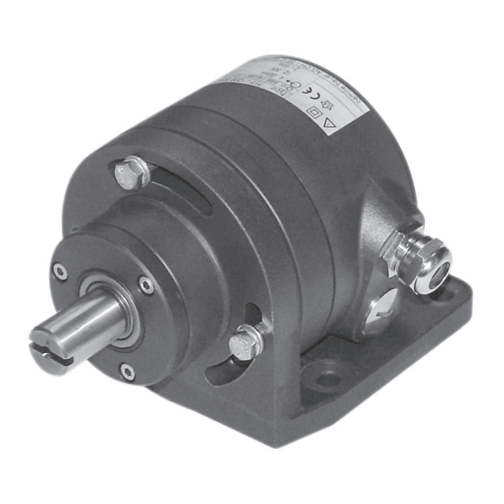
6. Mounting
The six versions of the transmitter differ in their mechanical
design. Two of them are intended for mounting directly on
the device being measured. The others are equipped with a
mounting bracket or a fl ange. The relationship between the
three types of mounting, or more precisely the corresponding
cut-out diagrams and the different versions of the transmitter
can be seen from Table 1.
Table 1:
Transmitter
versions
Three M6 screws are needed for the "directly" mounted ver-
sions and four M8 nuts and bolts for these "with a bracket"
or "with a fl ange". The screws, respectively nuts and bolts
are not supplied, because the required length varies according
to the thickness of the mounting surface.
When deciding where to install the transmitter
(measuring location), take care that the "ambient
conditions" given in Section "5. Technical data"
are not exceeded.
Make the cut-out or drill the holes in the item onto which the
transmitter is to be mounted according to the correspon-
ding drilling and cut-out diagram given in Table 1 and then
fi t the transmitter.
Drilling and cut-out diagrams
for mounting transmitters ...
±0.2
82
6.5
120º
±0.2
71
9
9
±0.2
130
7. Adjusting the angle
Angular position transmitters of the KINAX WT 717 range do
not require a mechanical zero position mark (however, this
is made if required by the customer, see Fig. 3a).
Fig. 3a.
Left:
for rotation transmitters with the range of 0 to ...
Right:
for rotation transmitters with V characteristic ranges.
Fig. 3b.
Sense of rotation seen from the shaft side:
Left: counterclockwise, right: clockwise.
During installation the shaft of the transmitter can be coupled
to the object to be measured in any position. Adjust the shaft
angle as follows with the 2W2 confi guration software:
1. Remove the cover (3.1 in Fig. 6). Remove the rubber co-
ver (5.1) to gain access the programming connector (5),
(see section "8.1 Connecting transmitter"). Connect the
KINAX WT 717 to the programming device according to
Fig. 4. Start the 2W2 confi guration software. If necessary,
confi gure the device with the required measuring range
data.
The angular position transmitter must only be
programmed outside of the Ex area!
Those max. angular speed of the wave may not
exceed 1 m/s
2. Place the measuring device in a defi ned position (prefere-
ably the zero position).
3. Select the "Adjustment" menu item under "SERVICE" in
the confi guration software. In the "Mechanical position"
window enter the current angle of the measuring device
and then select "Adjust". The measuring device is now
confi gured for the defi ned angle.
Programming
connector
KINAX WT717
Fig. 4
º,
Ancillary cable
Interface
PK 610
OFF
ON
OFF: Power supply
by measuring output
(Fig. 8)
ON: Power supply
provided by PC
15