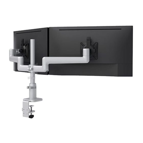
ESI KATAEX2-DC-FMS-WHT Руководство по установке - Страница 5
Просмотреть онлайн или скачать pdf Руководство по установке для Стойки и подставки ESI KATAEX2-DC-FMS-WHT. ESI KATAEX2-DC-FMS-WHT 12 страниц. Dual fixed+motion+slider monitor arm

KataEX2-FMS
Step #4: install monitor arm assemblies
• Monitor arm assemblies are installed by fitting the tabs on the end of the arm stems into slots on the connection sleeve, as shown in the top left illustration below.
— Typically, the arm stems are installed on opposite sides of the connection sleeve, at a 180° angle, with two empy slots between the arm stems.
— To project the monitors closer to the user, the arm stems may be installed at a 135° angle (one empty slot between arm stems) or a 90° angle (no empty slots
between arm stems). However, the fixed-motion arm combination already provides for a large projection; the difference among the angles is rarely significant.
• Install the monitor arm assemblies into the slots on the connection sleeve, with the arm stems at the angle you have chosen.
arm stem
slots
Step #5: secure monitor arm assemblies
• Carefully cut the decorative covers to remove them from the set. Slide the covers into the unused slots on
the connection sleeve.
• Lock the monitor arm assemblies to the connection sleeve with the locking ring. Rotate the locking ring
clockwise to secure it.
tabs
connection
sleeve
135°
arm stem
180°
90°
Page 5
decorative covers
turn locking ring
clockwise to lock
Assembly
