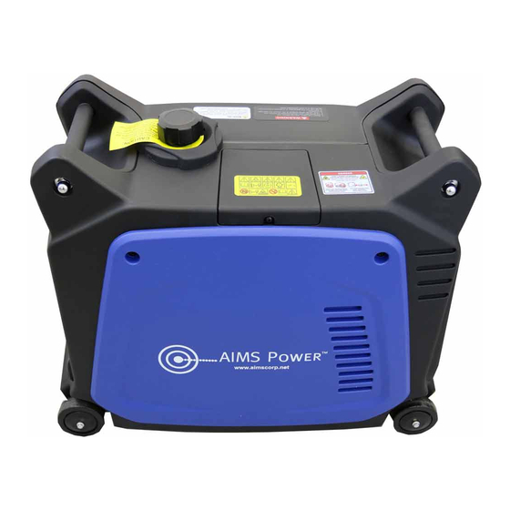
AIMS Power GEN3200W120V Руководство - Страница 11
Просмотреть онлайн или скачать pdf Руководство для Инвертор AIMS Power GEN3200W120V. AIMS Power GEN3200W120V 19 страниц. Portable inverter generator

OVERLOAD INDICATOR LIGHT
The overload indicator light comes on when an overload of a connected
electrical device is detected, the inverter unit overheats, or the AC output
voltage rises. The electronic breaker will then activate, stopping power to the
generation in order to protect the generator and any connected electric devices.
The output pilot light (green) will flicker and the overload indicator light (red) will
turn on, then the engine will stop running. If so please follow the following steps:
FIG.25
(a)
Turn off any connected electric devices and stop the engine
(b)
Reduce the total wattage of connected electric devices to within the generator's rated output.
(c)
Check for blockages in the cooling air inlet and around the control unit. If any blockages are found, remove.
(d)
After checking, restart the engine.
CAUTION:
The generator AC output automatically resets when the engine is stopped and then restarted.
The overload indicator light may come on for a few seconds at first when using electric devices that require a large
starting current, such as a compressor or a submergible pump. This is not a malfunction.
DC APPLICATION (option)
This applies to 12V battery charging only.
(a) Charging instruction for battery
Disconnect the leads for the battery.
For open lead acid batteries, remove caps.
Fill distilled water to the upper limit, if the battery fluid is low level.
Measure the specific gravity for the battery fluid by using the hydrometer,
and calculate the charging time in according with the table shown to the
right .
The specific gravity for the fully charged battery shall be within 1.26 to 1.28.
It is recommended to confirm every hour. FIG.26
(b) Connect between the DC output socket and the battery terminals using
the charging leads. The leads should be connected making sure the (+)
and (-) polarity are correct.FIG.27
(c) The DC circuit protector is to be set to "ON" after confirming the
10
FIG.25
FIG.26
Aim for specific gravity and charging time
1.30
1.26
2
1.22
1.18
1.14
1
1.10
1.06
0
2
4
Charging time Hr
Battery capacity
1. 30AH 20HR
2. 35AH 20HR
3. 47AH 20HR
FIG.27
OVERLOAD
3
6
8
10
