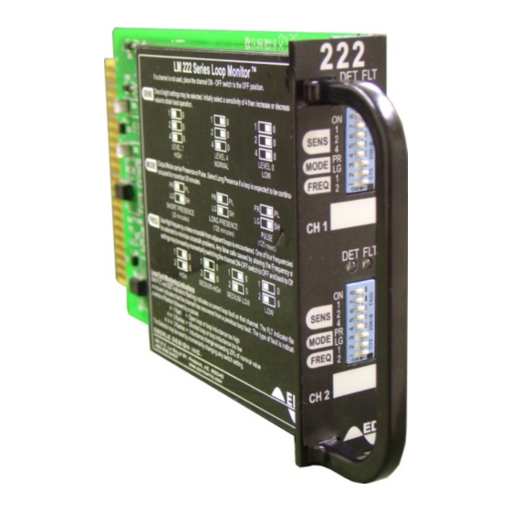
EDI 222 Series Руководство по эксплуатации - Страница 10
Просмотреть онлайн или скачать pdf Руководство по эксплуатации для Датчики безопасности EDI 222 Series. EDI 222 Series 17 страниц. Inductive loop detector sensor unit

1.8 SPECIFICATIONS
Power Supply:
24 VDC, 80mA maximum, 40mA quiescent.
Loop Input:
The loop inputs incorporate transient protection devices and the loop oscillator circuitry is
transformer isolated. The transient protection will withstand the discharge of a 10uF capacitor
charged to 2,000V across the loop inputs or between any loop input and earth ground. The
transformer isolation allows operation with loops which may be grounded at a single point.
Tuning:
Each channel of the Model 222 will automatically tune to any loop and lead-in combination
within the 20 to 2000 microhenry tuning range (Q factor greater than 5) upon application of
power or when a valid reset signal is received. A channel may be retuned by adjusting mode,
sensitivity or frequency.
Lead-in Length:
The unit will operate with lead-in (feeder) lengths over 1,000 feet with appropriate loops and
proper lead-in cable.
Environmental Tracking:
The Model 222 automatically and continuously compensates drift and environmental effects
throughout the tuning range and across the entire temperature range.
Grounded Loop Operation:
The Model 222 will operate when connected to poor quality loops including those that have a
short to ground at a single point.
Sequential Scanning:
Only one channel is energized at any given time, thus reducing the possibility of crosstalk
between adjacent loops connected to the same unit.
Fault Monitoring :
The Model 222 Loop Monitor continuously checks the integrity of the loop. The system is able
to detect shorted or open circuit loops, or sudden changes in inductance exceeding 25% of the
nominal value. If a fault is detected on a channel, the DET and FLT indicators will flash. The
channel output will remain in the detect (call) state.
i. One flash indicates an open circuit or a loop inductance exceeding the upper limit of the
tuning range.
ii. Two flashes indicate a short circuit or a loop inductance exceeding the lower limit of the
tuning range.
iii. Three flashes indicate that a sudden change in inductance exceeding 25% ∆L/L has
occurred.
If the fault condition is removed, the DET indicator and the channel output will return to normal
operation. The FLT indicator will continue to flash indicating that a fault had previously
occurred.
High Intensity LED Indicators:
Eberle Design Inc.
Model 222
Operations Manual
Page 8
