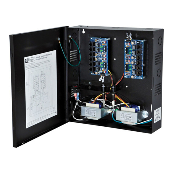
Altronix HubSat Series Руководство по установке - Страница 4
Просмотреть онлайн или скачать pdf Руководство по установке для Переключатель Altronix HubSat Series. Altronix HubSat Series 12 страниц. Passive utp transceiver hub with integral camera power

7 . Connect Video Balun/Combiner at camera 1 to the HubSat8DV unit utilizing CAT-5 or higher structured
cable . Plug the RJ45 connector at one end of a structured cable into the RJ45 jack marked [PVD1] of the
HubSat8DV (Fig. 1i, pg. 6) . Plug the RJ45 connector at the opposite end of the structured cable into the
RJ45 jack of the Video Balun/Combiner located at camera 1 .
•
For 24VAC cameras use Altronix model HubWayAv/HubWayAv2 Video Balun/Combiner
(Figs. 2a, 2b, 2e, pg. 7) .
•
For 12VDC cameras use Altronix model HubWayDv Video Balun/Combiner (Figs. 2c, 2d, pg. 7) .
•
For non-isolated 12VDC cameras use Altronix model HubWayDvi Video Balun/Combiner
(Figs. 2c, 2d, pg. 7) .
AC LED (Green) of the HubWayAv or DC LED (Red) of the HubWayDv Video Balun/Combiners will
illuminate indicating power is present at the cameras (Fig. 2b, 2d, pg. 7).
The total cable distance must not exceed 750 ft . for video transmission between the HubSat8DV and each
camera . Repeat this step for each additional camera [PVD2-8] .
8 .
Set illuminated master power disconnect circuit breaker to the RESET (ON) position (Fig. 3a, pg. 8) and
measure the output voltage at the power output of each Video Balun/Combiner (Figs. 2b, 2d, pg. 7) before
powering each camera to ensure proper operation and avoid possible damage .
9 .
Set illuminated master power disconnect circuit breaker to the (OFF) position (Fig. 3a, pg. 8) .
10 . Connect the power outputs of the HubWayAv or HubWayDv Video Balun/Combiners to the power inputs
of the cameras (Figs. 2a-2e, pg. 7). Polarity must be observed .
•
HubWayAv/HubWayAv2 - Terminals marked [AC POWER] (Figs. 2a, 2b, 2e, pg. 7) .
•
HubWayDv/HubWayDvi - Terminals marked [– 12VDC +] (Figs. 2c, 2d, pg. 7) .
11 . Connect the terminals marked [+ DATA –] of HubWayAv, HubWayAv2, HubWayDv or HubWayDvi
Video Balun/Combiners to data input terminals of cameras for PTZ control (Figs. 2a-2e, pg. 7) . Polarity
must be observed. When using fixed cameras disregard this step .
12 . Connect the BNC connector of HubWayAv, HubWayAv2, HubWayDv or HubWayDvi Video Balun/
Combiners to the BNC video outputs of cameras (Figs. 2a-2e, pg. 7) .
13 . Set illuminated master power disconnect circuit breaker to the RESET [ON] position (Fig. 3a, pg. 8).
14 . The power LEDs (Green) or Channels 1-8 of the HubSat8DV will illuminate when AC power is present
(Fig. 1e, pg. 6). If any of these LEDs are off, a loss of AC power output may be due to a blown fuse or a
tripped PTC caused by a short circuit or overload condition . If all of the LEDs are OFF there may be a
complete loss of supply power to the HubSat8DV unit or the illuminated master power disconnect circuit
breaker is in the OFF position or the primary in-line fuse is blown .
To restore the power output for HubSat8DV:
1 - Switch corresponding output voltage switch to the OFF position (Fig. 1d, pg. 6) .
2 - Eliminate the trouble condition .
3 - Allow 1 minute for PTC to cool off .
4 - Switch output voltage switch to the 24VAC or 28VAC position as desired (Fig. 1d, pg. 6) .
HubSat8DV for use as a Remote Accessory Module with HubWay/HubWayLD/HubWayLDH UTP Transceiver Hubs.
After completing steps 1-4 of Installation Instructions for HubSat8DV Passive UTP Transceiver Hub with
Integral Camera Power proceed with the following .
1 . For fixed cameras run two (2) CAT-5 cables between HubSat8DV and HubWay, HubWayLD or
HubWayLDH to allow video transmission of up to eight (8) cameras . For PTZs run three (3) CAT-5
cables between HubSat8DV and HubWay, HubWayLD or HubWayLDH (Fig. 5, pg. 9) .
a . Connect one (1) of the CAT-5 cables to the RJ45 jack marked [Video 1-4] on Circuit Board A .
Connect the opposite end of this CAT-5 cable into the RJ45 jack marked [CH 1-4] of HubWay,
HubWayLD or HubWayLDH unit (Fig. 5, pg. 9) .
b . Connect the second CAT-5 cable to the RJ45 jack marked [Video 1-4] on Circuit Board B . Connect the
opposite end of this CAT-5 cable into the RJ45 jack marked [CH 5-8] of HubWay, HubWayLD or
HubWayLDH unit (Fig. 5, pg. 9) .
c . For data (PTZ) connect the third CAT-5 cable to the RJ45 jack marked [Data 1-4] on Circuit Board A .
Connect the opposite end of this CAT-5 cable into any unused RJ45 jack marked [1-16] of HubWay,
HubWayLD or HubWayLDH unit (Fig. 5, pg. 9) .
Note: Data inputs of HubWay, HubWayLD or HubWayLDH units must be wired in parallel for proper
operation . When using fixed cameras disregard this step .
2 .
Plug the RJ45 connector at one end of the CAT-5 or higher structured cable into the RJ45 jack marked
[PVD1] on Circuit Board A (Fig. 1i, pg. 6) . Plug the RJ45 connector at the opposite end of the CAT-5 or
higher structured cable into the RJ45 jack of the Video Balun/Combiner to be installed at camera 1 .
•
For 24VAC cameras use Altronix model HubWayAv/HubWayAv2 Video Balun/Combiner
(Figs. 2a, 2b, 2e, pg. 7) .
•
For 12VDC cameras use Altronix model HubWayDv Video Balun/Combiner (Figs. 2c, 2d, pg. 7) .
•
For non-isolated 12VDC cameras use Altronix model HubWayDvi Video Balun/Combiner
(Figs. 2c, 2d, pg. 7) .
- 4 -
HubSat8DV
