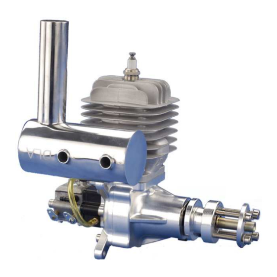
DLA DLA56 Руководство пользователя - Страница 3
Просмотреть онлайн или скачать pdf Руководство пользователя для Двигатель DLA DLA56. DLA DLA56 5 страниц. Toplevel gasoline engine
Также для DLA DLA56: Руководство пользователя (7 страниц)

3.
In order
to
make sure the engine does not speed
exces
sively
without a positive control installed ,throttle return
sprin
gs must
be left
in
place.
4
.
Afte
r you have connected the return spring to the
th
rottle servo
you may unhook it
(
do not remove
it)
,since
it
acts as
a spacer
for
the
butterfly. The butterfly will work
loose
by
removing the
return
spring.
5.
The
ignition battery should be mounted externally,
near the cowl,
at
least twelve inches from the
receiver
or
throttle
servo
that
connects to the
receiver.
6.
The
carburetor needs at least
1
1/2" (38mm) o
f
clearance
between
the intake
and the bottom of the cowl.
If
there is less
th
an
1
1/2",
make an opening in the cowl below
the carb at
least
as
large as the carb intake diameter.
7.
A long
,
narrow, screw driver is recommend to
drill
small holes
in the cowl for adjusting
the
needle valves, since the
carburetor
must
often
be
adjusted differently with the cowl on
as compared
to
off.
8.Th
ese
eng ines burn
between
one and
two
ounces
of
fuel per
minute.
Therefore, a 32 ounce or
larger
tank
is
recom
mended.
The
engines are equipped
with
a
diaphragm pum
p carburetor
making
tank
location not critical relative
to
th
e
carb
ure
tors fuel
entry position. Place
the
tank on the
aircraft's ce nte
r of gravity
(CG). Then ai rcraft trim
changes
during
fl
ight wi
ll not be
necessary
from a
full
to
an
empty
tank.
Fuel:
Clea
n
petrol
93#
is strongly
recommend
for your
DLA engines.
Lubrication
Ratio of trial Run is 30: 1
while
normal
flyi
ng
is 40: 1,
Higher-octane fuel wi
ll not
generate
more
pow
er
and may cause
the
engine to
run
slower
and
overh eat.
Note: Damage
caused by fuel
additi
ves, su
ch as
nitro, over-lean
carb
setting
s,
over-ad
vanced timing,
and over-heating are not
covered under wa
rranty.
Ign ition
system
It
is
im portant to
understand
how the ignitio
n
system
is
to
be
wired. Mount the ignition module usi
ng
the
four supplied
rubbe
r
grommets so as to create a 1/16" gap
between the ignition
module
and the mounting surface. Without
th
is
1/16"
gap the ignition
module can overheat.
Important: If the electronic ignition
overheats
it will malfunction
(e.g., backfiring or shutting down).
Ignition details:
• The red cable is positive
(+),while
the black is negative(-).
• Working voltage
:
4 .8v-6v.
• It is important to achieve the correct coordination of the sensor(s)
,
1
to the magnets for fitting a new ignition.
The propeller
selection and
installation
Make sure the prop, spinner and prop bolts before each flight!
Loose prop bolts allow prop movement which will shear the bolts.
Selection:
• The following props are recommended: 22cm*8cm, 22cm*10cm
• Only use propeller sizes that are recommed above for your engine.
• The propeller blades must be of the same length
.
Installation:
• You must use a drill press to drill your propeller from the rear.
• A drill guide is recommended
,
but the propeller washer can be
used as a drill template. (Fix the propeller washer onto the
propeller in the center-bore using a bolt and nut.)
• keep your propeller balanced.
Engine starting
procedure
1. Fill the tank with fresh filtered fuel.
1
2. Insure that your receiver and ignition batteries are charged, your
j
receiver and transmitter are on. and that your throttle is set to low.
3. Close the choke and turn on the ignition switch.
4. Rubber stick is recommend to start the engine.
5.
Begin flipping the prop through its compression stroke until the
engine fires.
6. Wait for the propeller to stop spinning, turn off the ignition, and
open the
choke(s).
