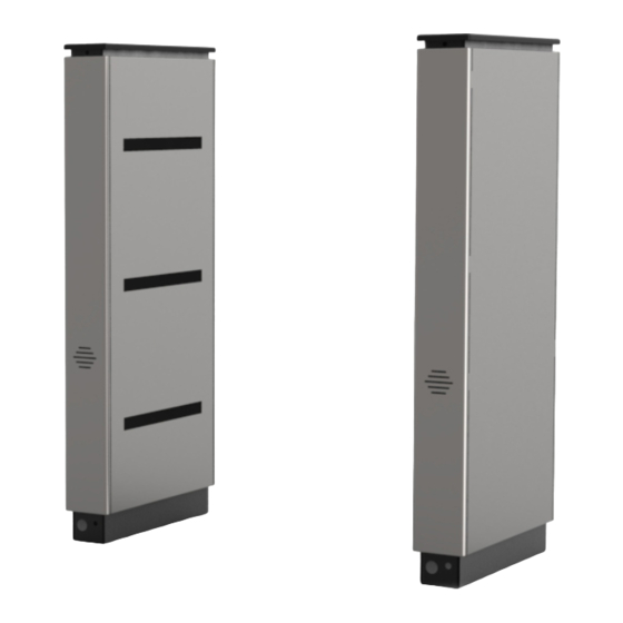
Alvarado Supervisor 500 Руководство по установке - Страница 7
Просмотреть онлайн или скачать pdf Руководство по установке для Турникеты Alvarado Supervisor 500. Alvarado Supervisor 500 19 страниц. Barrier-free optical counting turnstile

Pre-Installation Instructions
NOTE
It is assumed that the Pre-Installation Checklist steps are complete.
Side Panel Removal
1.
To remove a side panel, slide the side panel up until it
clears the pins, then pull straight out [Figure 8].
NOTE
Do not force open the side panels. Use a screwdriver to
carefully loosen any tight fitting side panels. Take care when
doing this to prevent damage to the unit.
Lid Removal
1.
Locate the lid screws located on the cabinet end panels as
shown in [Figure 9]. There is one lid screw per side.
2.
Using a #2 Phillips head screwdriver, remove the two (2) lid
screws.
3.
Gently lift the lid in an upward motion to remove.
Page 12
For Assistance: [email protected] +1 (909) 591-8431
SU500 Installation Instructions
Figure 8
Side Panel Removal
2
1
Figure 9
Lid Removal (Side View)
Lid
Screw
PUD1456R5-0
SU500 Installation Instructions
Turnstile Layout
With the panels and lids removed, confirm that the cabinets are laid out such that one side of the lane contains the master controller
cabinet components and the other side of the lane contains the slave cabinet components. The correct layout orients the power
button on the exit side as shown in [Figure 10]. An example of an incorrect layout is shown in [Figure 11]. Before proceeding, verify
that the master controller cabinet components are facing the slave cabinet components, and the power button(s) are located on the
secured side. The Lane 1 master cabinet is always the right-most cabinet when viewed from the entry side of the turnstile.
Figure 10
Correct Turnstile Layout
CORRECT
LANE 2
Figure 11
Incorrect Turnstile Layout (Lanes Oriented Backwards)
INCORRECT
LANE 1
Power
Button
PUD1R5-0
For Assistance: [email protected] +1 (909) 591-8431
Exit Side
The power button should always be
located on the exit side.
Power
Button
LANE 1
Entry Side
Exit Side
LANE 2
Power
Button
Entry Side
Power
Button
Page 13
