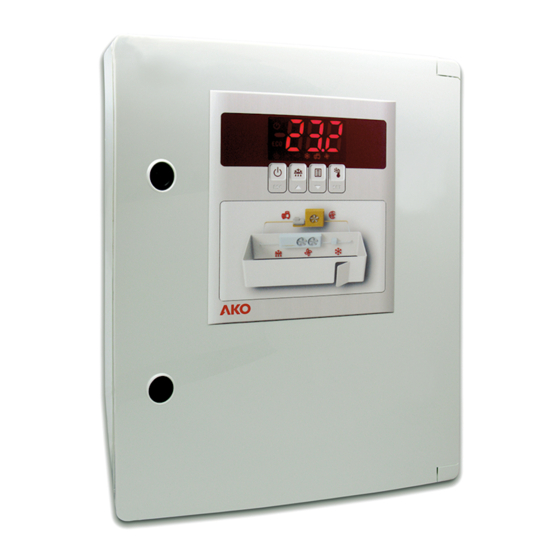
AKO PROCool AKO-17632 Краткое руководство
Просмотреть онлайн или скачать pdf Краткое руководство для Панель управления AKO PROCool AKO-17632. AKO PROCool AKO-17632 4 страницы. Electronic panel

PROCool Electronic Panel
AKO-17632, AKO-17633, AKO-17634, AKO-17635, AKO-17636, AKO-17637, AKO-17520, AKO-17521
Quick guide
Maintenance
Clean the surface of the unit with a soft cloth, water and detergent. Do not use abrasive
detergents, petrol, white spirits or solvents.
Precautions
Using the equipment without following the manufacturer's instructions may affect the
device's safety requirements. To ensure that the device operates correctly, only probes
supplied by AKO should be used.
Between -40 ºC and +20 ºC, if the NTC probe is extended up to 1,000 m with minimum
0.5 mm² wire, the maximum deviation will be 0.25 ºC (Wire for probe extension ref.
AKO-15586)
IMPORTANT:
The function of the digital inputs depends on the configuration.
Ÿ
The recommended currents and powers are the maximum working currents
Ÿ
and powers.
Description
Stand-by active mode
Alarm active
Compressor active (If P26=1)
Condenser fans
active
Display
Stand-by key
Defrost key
Key function
Pressing it for 5 seconds activates the Stand-By mode. Pressing it for 2 seconds the unit
returns to the normal mode. In Stand-by mode, the unit performs no action and the
display only shows the m indicator along with the temperature.
ESC
During configuration, it exits the parameter without saving changes, returns to
previous level, or exits programming.
One short press* shows the non-displayed probe reading (see P8 parameter).
Pressing it for 5 seconds starts/stops the defrost.
During configuration, it allows you to scroll through the different levels, or when
setting a parameter, to change its value.
Pressing for 5 seconds accesses the quick configuration menu.
Pressing for 10 seconds accesses the advanced configuration menu.
During configuration, it allows you to scroll through the different levels, or when
setting a parameter, to change its value.
One short press* displays the current set point value (SP).
Pressing it for 5 seconds accesses change set point.
During configuration, it accesses the level shown on the display or, when setting a
SET
parameter, it accepts the new value.
*Short press: Less than 5 seconds.
Messages
L5
E1 / E2
dEF
AH
AL
Temperature
AE
AES
Adt
Defrosting in progress
Evaporator fans active
Solenoid active
PAb
Pd
LP
Set Point key
Menu key
ASC
Quick configuration
The quick configuration menu allows the unit to be configured for the most common
applications. Press the
SP: Set point
It sets the coldroom's working temperature
d0: Defrost frequency
Time that must elapse between the starting of each defrost.
d1: Maximum defrost duration
The defrost will end after this time has elapsed since it started.
F3: Fan status during defrost
It defines the status of the fans during defrost.
A1: Maximum alarm probe 1
Defines the temperature at which the maximum alarm will be triggered. Only affects probe 1.
A2: Minimum alarm probe 1
Defines the temperature at which the minimum alarm will be triggered. Only affects probe 1.
P26: Stoppage owing to pump down
It defines whether this function is active
1
Flashing 0: Access code (Password) request
You must enter the access code configured on L5 to execute the requested
function. See also parameter P2.
Probe 1 or 2 faulty (open circuit, crossover or temperature outside the
probe limits; NTC: -50 To 99 ºC).
Indicates a defrost is underway. When the defrost process has finished, the
message will continue to be displayed during the time defined in
parameter d3.
Alternating with temperature:
Maximum temperature in control probe alarm. Temperature set in A1 has
been reached.
Alternating with temperature:
Minimum temperature in control probe alarm. Temperature set in A2 has
been reached.
Alternating with temperature:
External alarm activated (by digital input).
Alternating with temperature:
Severe external alarm activated (by digital input).
Alternating with temperature:
Defrost alarm time-out. Displayed when a defrost ends after the maximum
time elapsed as defined in parameter d1.
Alternating with temperature:
Door open alarm. Shown if the door remains open longer than specified in
parameter A12.
Alternating with temperature:
The maximum pump down stop time has been exceeded (P15)
Alternating with temperature:
The maximum pump down start-up time has been exceeded (P14).
It indicates that a component in the compressor's safety chain has
triggered (compressor motor guard, thermistors or high pressure
controller).
key for 5 seconds to access it.
0= Stopped
Ÿ
1= Running
Ÿ
0= Without pump down
Ÿ
1= With pump down
Ÿ
GB
1763H202 Ed.02
