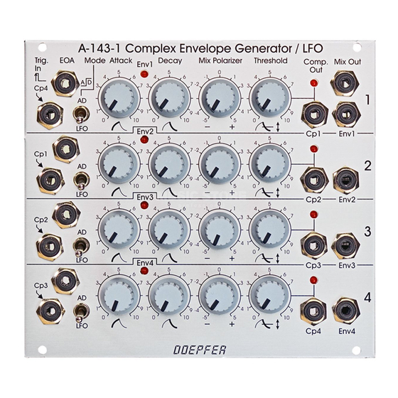
DOEPFER Quad AD/LFO A-143-1 Руководство - Страница 7
Просмотреть онлайн или скачать pdf Руководство для Блок управления DOEPFER Quad AD/LFO A-143-1. DOEPFER Quad AD/LFO A-143-1 8 страниц.

DOEPFER
Technical note:
The envelope output (socket
the factory. Optional the output can be modified to "post
polarizer" by means of an internal wire jumper. For details
please refer to the technical document A143_1_jumpers.pdf
on our website. When set to "post polarizer" the signal
§
appearing at socket
%
signal (socket
Mix Out).
4
Mix Polarizer: polarizer control
This control is used to add or subtract the envelope signal of
the corresponding unit to/from the mix signal appearing at
output %. This control is a so-called polarizer. The neutral
position of the polarizer knob is at its center (0). Left from
the center (area marked with a minus sign) the envelope
signal of the unit is subtracted from the mix signal. Right
from the center (area marked with a plus sign) the envelope
signal of the unit is added to the mix signal. The distance
from the center position determines the adding/subtracting
level.
System A-100
§
) is set to "pre polarizer" in
is inverted with regard to the mix
Quad AD/LFO A-143-1
5
Threshold:
threshold control for comparator
$
Cp x:
comparator output (x = 1...4)
7
:
comparator output display (LED)
5
The threshold control
level of the comparator. The threshold setting defines the
behaviour of the corresponding comparator output (Cp x).
This output turns "low" as soon as the level of the envelope
signal exceeds the threshold level. Otherwise it's high.
Please refer to the page 2 for details.
"
EOA :
end of attack output
This is the digital End Of Attack output (EOA). The EOA
output is low during the attack stage and high otherwise. It
can be used to trigger other A-100 modules or other units of
the A-143-1.
%
Mix Out:
mix output
This is the sum output where all envelope signals are added
or subtracted in accordance to the corresponding polarizer
controls. It can be used as a complex envelope signal (all
mode switches in AD position and an external trigger signal
connected to one of the trigger inputs) or as complex LFO
(same as before, but no trigger signal connected to one of
the trigger inputs).
is used to adjust the threshold
7
