Aseptico ADU-40CF Command Air Руководство по эксплуатации, техническому обслуживанию и ремонту - Страница 5
Просмотреть онлайн или скачать pdf Руководство по эксплуатации, техническому обслуживанию и ремонту для Медицинское оборудование Aseptico ADU-40CF Command Air. Aseptico ADU-40CF Command Air 16 страниц. Portable field sink
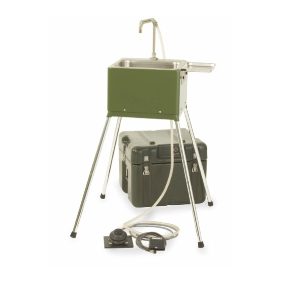
Assembly
1. After removing the ADU-40CF Command Air Field Sink from its original packaging, unfasten all
perimeter latches and remove the cover. Locate the accessory pouches and lift the sink from the
carry case. Refer to Figure A
2. Remove the four collapsible legs from the legs pouch and unfold. Make sure the locking dowel
engages completely. Insert the legs into the guide tubes on the
underside of the sink chassis and twist to engage the lock-pin and
secure.
3. Optional Leg-Support Kit (AA-04CF): Refer to Figure F
a) Remove the black rubber feet from the existing sink legs.
b) Unfold the optional leg support sections and join together
to make two complete supports.
c) Insert right front sink leg into white plastic knuckle on end
of optional support. Insert right rear sink leg into other end
of support. Repeat on left side of sink with second support.
(Note: The leg supports will also function properly when
installed between the two front sink legs and two back legs.)
4. Raise the sink spout to the fully extended position. Refer to Figures G1 & G2
Storage
Position
5. Remove the contents of the plumbing pouch. Attach the intake hose assembly to the quick
connect, labeled "WATER INPUT" on the underside of the
sink. Immerse the hose weight in the source jerry can (not
provided) to the preset distance and secure the line using the
attached push-on cap. Refer to Figure H
6. Attach the waste hose to the underside of the sink. Place the
opposite end in a waste water jerry can (not provided). Secure
the line using the push on cap. Refer to Figure H
7. If desired, attach the components of the cold water pump
assembly (refer to Figure E) to dispense cold water.
a) Unpack the manual foot pump and tubing assembly.
b) Attach the hose adapter to the sink spigot. Refer to Figure I
c) Place the foot pump on a level section of ground and attach the
Hose Adapter
Instrument
Tray
Figure I - Spout Connection
Operation
Position
Figure G1 - Spout Position
other end to water source. Prime the lines
by depressing the foot pump several times, until water flows into the sink.
Refer to Figure E
8. Remove the contents of the electronics pouch. Attach the electric
ON/OFF foot switch to the foot switch connector, labeled "FOOT
SWITCH", on the underside of the sink. Refer to Figure H
9. Select the appropriate power cord for the power source. Connect the cord
on the underside of the sink and secure it using the retaining clip connector.
Plug the other end into the power source. The sink will operate on either a
120V or a 230V power supply. The green L.E.D. by the spout will light
indicating power. Refer to Figure H
Figure F - Optional Leg Supports
Storage
Position
Figure G2 - Optional AA-04EXS 15-Inch Spout Position
Grounding Stud
Optional
Leg Supports
Assembled
Operation
Position
Figure H - Connections
Page 5