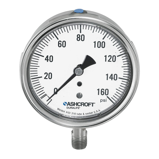
Ashcroft DURALIFE 1009 Руководство по установке, эксплуатации и техническому обслуживанию - Страница 8
Просмотреть онлайн или скачать pdf Руководство по установке, эксплуатации и техническому обслуживанию для Измерительные приборы Ashcroft DURALIFE 1009. Ashcroft DURALIFE 1009 20 страниц. Pressure gauge

4.5 Other considerations – These include (a)
bent or unattached pointers due to extreme
pressure pulsation; (b) broken windows which
should be replaced to keep dirt out of the
internals; (c) leakage of gauge fill; (d) case
damage – dents and/or cracks; (e) any signs of
service media leakage through the gauge
including its connection; (f) discoloration of
gauge fill that impedes readability.
4.6 Spare parts – As a general rule it is rec-
ommended that the user maintain in his
parts inventory one complete Ashcroft
instrument for every ten (or fraction thereof)
of that instrument type in service.
5.0 GAUGE REPLACEMENT
It is recommended that the user stock one
complete Ashcroft
®
instrument for every ten
(or fraction thereof) of that instrument type in
service. With regard to gauges having a ser-
vice history, consideration should be given to
discarding rather than repairing them.
Gauges in this category include the following:
a. Gauges that exhibit a span shift greater
than 10%. It is possible the Bourdon tube
has suffered thinning of its walls by corro-
sion.
b. Gauges that exhibit a zero shift greater
than 25%. It is likely the Bourdon tube
has seen significant overpressure leaving
residual stresses that may be detrimental
to the application.
c. Gauges which have accumulated over
1,000,000 pressure cycles with significant
pointer excursion.
d. Gauges showing any signs of corrosion
and/or leakage of the pressure system.
e. Gauges which have been exposed to high
temperature or simply exhibit signs of
having been exposed to high temperature
– specifically 250°F or greater for soft sol-
dered systems; 450°F or greater for brazed
systems; and 750°F or greater for welded
systems.
f. Gauges showing significant friction error
and/or wear of the movement and linkage.
g. Gauges having damaged sockets, especially
damaged threads.
h. Liquid filled gauges showing loss of case
fill.
NOTE: ASME B40.1 does not recommend
moving gauges from one application to anoth-
er. This policy is prudent in that it encourages
the user to procure a new gauge, properly tai-
®
lored by specification, to each application that
arises.
6.0 ACCURACY:
PROCEDURES/DEFINITIONS
Accuracy inspection – Readings at approxi-
mately five points equally spaced over the
dial should be taken, both upscale and down-
scale, before and after lightly rapping the
gauge to remove friction. A pressure standard
with accuracy at least 4 times greater than
the accuracy of the gauge being tested is rec-
ommended.
Equipment – A finely regulated pressure sup-
ply will be required. It is critical that the pip-
ing system associated with the test setup be
leaktight. The gauge under test should be
positioned as it will be in service to eliminate
positional errors due to gravity.
Method – ASME B40.1 recommends that
known pressure (based on the reading from
the pressure standard used) be applied to the
gauge under test. Readings including any
error from the nominal input pressure, are
then taken from the gauge under test. The
practice of aligning the pointer of the gauge
under test with a dial graduation and then
reading the error from the master gauge
("reverse reading") can result in inconsistent
and misleading data and should NOT be used.
8
