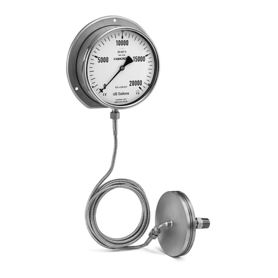
Ashcroft TC Инструкции по установке и обслуживанию
Просмотреть онлайн или скачать pdf Инструкции по установке и обслуживанию для Измерительные приборы Ashcroft TC. Ashcroft TC 4 страницы. Tank level gauge

Installation and Maintenance Instructions
for the TC Tank Level Gauge
Before using the pressure gauge
it is highly recommended that this
instruction manual be thoroughly
reviewed to prevent improper
instrument handling and/or
implementation. Consult Ashcroft
on related topics not covered
within this document
Table of contents:
1. INTRODUCTION ................................................................. 2
2. APPLICATION ..................................................................... 2
3. TRANSPORTATION, STORAGE & UNPACKING
PRECAUTIONS ................................................................... 2
4. DRAWING ............................................................................ 2
5. INSTALLATION .................................................................... 2
6. MAINTENANCE ................................................................... 3
7. TROUBLESHOOTING ......................................................... 3
1. INTRODUCTION
Pressure measurement is an important aspect of manufacturing.
This manual describes the basic operation of the Ashcroft TC
Tank Level Gauge, Designed specifically for vented tanks, the
following instructions should be followed to ensure effective
operation of the gauge.
[Before Using the Pressure Gauge]
It is highly recommended that this instruction manual will be
thoroughly reviewed to prevent improper instrument handling
and/or implementation. Consult Ashcroft on related topics not
covered within this document.
2. APPLICATION
The TC Tank Level Gauge continuously measures liquid
contents of any shape of storage tank or vessel, while its
integral capillary line facilitates remote mounting/reading of
the indicating dial. This gauge offers internal or external tank
mounted seal housing, and multiple mounting options.
This product was designed with a 160mm analog dial. Dials are
graduated in units to user specifications and are often marked
with radial lines to denote critical tank levels.
© Ashcroft Inc. 2020, 250 East Main Street, Stratford, CT 06614-5145, USA, Tel: 203-378-8281, Fax: 203-385-0357, www.ashcroft.com
All sales subject to standard terms and conditions of sale. Tank_Content_Gauge_im_RevA_(I&M008-10279)_07-23-20
The power required to operate the TC Tank Level Gauge is
derived from the pressure exerted by the head of liquid within
the tank (hydrostatic pressure). This pressure is sensed by a
stainless steel diaphragm incorporated into the seal housing;
pressure is then conveyed by capillary line to a capsule that
drives the indicating pointer.
Deflection of the capsule within the indicator actuates a
precision mechanism, which moves the a pointer over a
calibrated scale. The transmitting diaphragm, capillary and
indicator capsule together form a sealed system, which is
thoroughly examined for leaks. No attempt should be made
to disconnect the capillary from the instrument, except for
mounting; this minimizes the risk of leaking and/or malfunction.
3. TRANSPORTATION, STORAGE & UNPACKING
INSTRUCTIONS
3.1 Transportation
Units should be handled with care. Be very careful not to apply
vibration to the pressure gauge during transportation.
Never hit or drop the pressure gauge.
CAUTION
The instrument may incur damage if dropped or impacted.
3.2 STORAGE
Store in a temperature-controlled environment free from
dust, humidity, and vibration.
3.3 UNPACKING
Handle the instrument with great care during unpacking.
Verify the product has not been damaged and that the
instrument fulfils the required specifications.
4. MOUNTING
INTERNAL
INTERNAL
Typical mounting positions on vented tanks
EXTERNAL
EXTERNAL
1
