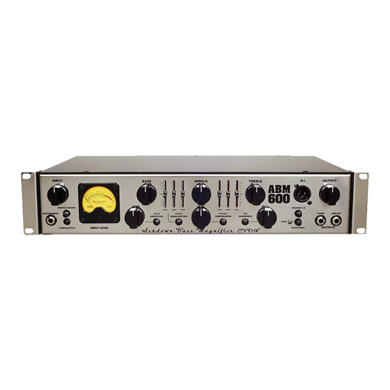
Ashdown ABM-EVO-IV-600RC Руководство пользователя - Страница 3
Просмотреть онлайн или скачать pdf Руководство пользователя для Усилитель Ashdown ABM-EVO-IV-600RC. Ashdown ABM-EVO-IV-600RC 7 страниц. Ashdown engineering amplifier abm-evo-iv

ABM-EVO-IV - Front Panel Facilities
INPUT
BASS
PUSH FLAT/SHAPE
INSTRUMENT
VALVE
DRIVE PLUS
EQUALISATION
INPUT LEVEL
PASSIVE/ACTIVE
the two sets of sliders interposed between these
controls set in their centre positions and using
only the BASS, MIDDLE and TREBLE controls
to alter the overall tone.
Secondly, if more control is required then the
sliders can also be used to tailor the E.Q. in the
regions between the main tone controls. This
provides a very versatile Equalisation section,
it is simple to understand and operate, yet
provides a wide degree of variation. It retains
the simplicity of a three- control tone section but
provides the flexibility of a graphic equaliser.
DYNAMIC COMPRESSION – Adding a small
amount of compression gives a fat bottom end to
the sound and allows a greater volume of ampli-
fication to be used without the playing peaks dis-
torting the amplifiers output stage. You will also
find that this will add definition to your playing
bringing out notes within a run more clearly as it
evens out the dynamics of your playing.
A large amount of compression can be used as
an effect but it will tend to reduce the dynamics
in your playing to such an extent that the volume
of the note will be the same no matter how hard
or soft you hit the string. Compression also adds
sustain to notes making them longer before they
die away.
The Compression Level control adjusts the de-
gree of compression applied to the bass signal.
For this to function correctly the Input Level must
MIDDLE
TREBLE
D.I.
OUTPUT
PRE/POST E.Q
9 BAND
DYNAMIC
SUB
TUNER
LINE OUT
COMPRESSION
HARMONICS
MUTE
OUTPUTS
OUTPUT MUTE
be correctly set as described in the INPUT
CONTROL section (left).
When the Input Level is correctly set there will
be hardly any difference in volume between
Compression IN and Compression OUT. This
is because the amplifier automatically com-
pensates for the reduction in level that would
be apparent when Compression is added by
increasing the overall gain to restore the vol-
ume to its pre compression level, because of
this you may notice an increase in background
noise with high compression settings.
COMPRESSION IN/OUT – This push button
switches the Compression IN or OUT. This
function may also be controlled from the Ash-
down 4 way footswitch. For the footswitch to
operate this button must be in its OUT position.
SUB HARMONICS - This section produces
Sub Harmonics an octave below the notes
being played. The level of these Sub Harmon-
ics relative to the straight bass sound can be
adjusted using the LEVEL control.
This is very effective in thickening the sound
and you will find in use that only a small de-
gree of this lower octave is required to really fill
out the sound and provide a character that is
not possible by any other means.
The degree of Sub Harmonics is also depend-
ant on the setting of the BASS control.
DIRECT INJECT (D.I.) - A balanced D.I. is pro-
vided on a latching XLR socket. This has a push
button placed below it that allows the user to
choose either a Pre E.Q. signal (button pushed
IN) or a Post E.Q. Post Sub and effects signal
(button OUT).
The output signal from this XLR socket is set to
a level and impedance suitable for connecting
directly into the Microphone input of a mixing
desk for either Direct Injection into the PA system
or for recording. This must ONLY be used into a
Balanced Microphone input, it is not intended for
any other type of connection.
This has a floating ground that is referenced to
the mixing console it is plugged into and should
not need ground lifting. It is also unaffected by
Phantom Powering on the Microphone input.
Make sure your XLR plug does not have the
shell of the plug internally connected to signal
ground or this will connect the system to chassis
ground of the ABM and may cause problems
with hum.
PUSH TO MUTE - When pushed IN this button
mutes the output from the preamp to the power
amp, mutes the output from the D.I. socket and
mutes the output from the LINE Out socket as
well. This leaves the output from the TUNER
socket still available to allow muted tuning.
A blue LED is provided next to this switch to in-
dicate when the amplifier is muted. This function
operates only from the front panel MUTE push
switch. i.e. pressing this button mutes all sound
from the amplifier and allows a tuner connected
to the TUNER socket to operate for silent tuning.
Release the button and you are back in action
again.
TUNER OUT - This output socket provides
a line level signal that can be used for a perma-
nent connection to a tuner.
The signal from this socket remains when all
other outputs from the amplifier are Muted
allowing all sound from the amplifier to be
silenced while tuning is in progress.
LINE OUT -This output socket provides a line
level/post Output Level control signal for con-
nection to an external power amplifier driving
additional speaker cabinets.
OUTPUT LEVEL - The OUTPUT control
adjusts the overall level of the amplifier. Adjust
this for your preferred overall stage playing
volume.
