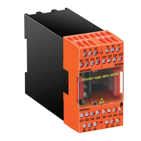
DOLD SAFEMASTER M BG 5913.08/00MF0 Техника безопасности - Страница 3
Просмотреть онлайн или скачать pdf Техника безопасности для Системы ввода/вывода DOLD SAFEMASTER M BG 5913.08/00MF0. DOLD SAFEMASTER M BG 5913.08/00MF0 12 страниц.

automatic start
Automatic start is performed only when supply voltage is switched on, or
when the emergency stop or stop function has been reset.
All other errors nevertheless require confirmation by a start input.
Manual Start
To start the system, do not keep the start key pressed for more than 3
seconds. A module may also be assigned several start keys.
One-channel input
With setting 6), it is imperative to use a voltfree contact for the single contact.
A static signal cannot be used.
Simulation input for function of safety gates
When the unit is set to monitor safety gates according to EN 201 switch
position 4, 5, 6 and 7, closing of the assigned safety outputs is only enabled,
if every gate has changed from open state (all contacts inactive) to closed
state within a maximum period of 3 sec on each gate.
When the system is powered up with some gates open and some closed
the open gates can be closed and the system can be started up by the
simulation button, simulating an open-close cycle of the previously closed
gates.
Only those gates are simulated, that had been closed before the system
was powered up.
Simulation is only possible once after the unit is powererd up. After that all
contacts of a gate have to be opened and reclosed to enable the outputs
again. When closing the gate all contacts of a gate have to close within
3 sec.
Function of the Two-Hand Control
Up to 4 pairs of two-hand safety circuits can be connected with the two-
hand safety function. However, no more than one circuit may be activated.
To permit enabling of the assigned safety outputs, the following conditions
must be fulfilled:
1) First, none of the connected two-hands circuits must be activated.
2) Both buttons of a two-hand control must be pressed within 0.5 s.
3) When changeover contacts (type IIIC acc. to DIN / EN 574) are used
for the two-hand-safety buttons, they must effect change over of con-
tacts within 50 ms.
4) As soon as a button of a second two-hand circuit is pressed, the
outputs are disabled, and condition 1) must be fulfilled once more
before a new enabling cycle can start.
5) The two-hand buttons habve to be released if an other function mo-
dule, also assigned to the same outputs disables the outputs.
6) Only one two-hand control module is allowed in one safemaster m
system.
The unit must be connected as specified in the application examples. When
the operating contacts are connected in parallel or in series, safe functioning
of the unit is cancelled.
The two-hand buttons must be designed and arranged in such a
way as to ensure that they cannot be disabled easily, or pressed
unin ten tionally.
The safety distance between the push buttons and the place of danger must
be large enough to insure that after releasing a button, the place of danger
can only be reached after the dangerous movement has stopped.
The safety distance "S" is calculated according to the following formula:
Function of the Two-Hand Control
S = V x T + C, where
a) gripping velocity V = 1 600 mm/s
b) overtravel time T (s)
c) and safety factor C = 250 mm.
When any access into the dangerous area, with operating keys pressed,
is safely prevented, e.g. by a protective cover for the keys, the safety factor
C may be set to the value 0. Generally, the minimum safety distance must
be 100 mm. See also DIN/EN 574.
Safety gate function
The safety gate function always permits enabling if both contacts change
from inactive to active state within 3 seconds. If the second contact reacts
later, both changeover contacts must turn inactive before they can be
enabled again.
When activating the system, press the start button to simulate the compul-
sory opening and re-closing of safety gates which have been kept closed
since the system has started.
This simulation is possible only before enabling has been permitted for
the first time, and as long as both safety gate contacts remain closed as
well. As soon as a contact opens, simulation of the safety gate function is
no longer possible.
emergency Stop or Light Curtain (LC) Function
In the Emergency stop or LC functions, both signals have to change from
inactive state into active state within 250 ms. If the second signal reacts
later, both changeover contacts must turn inactive before they can be
enabled again.
With manual start, all safety inputs must be active before the start button
can be pressed to trigger enabling. To start the system, do not keep the
start button pressed for more than 3 seconds. A module may also be as-
signed several start buttons.
Note:
Connect only self-testing light curtains of the type 4 acc. to EN
61496 to the module. Short-circuit monitoring of the inputs for
the LC must be done in the LC.
Indication of System errors:
These errors are indicated by flashing codes of the white LEDs Run 1 and/
or Run 2. The green LEDs and all outputs turn inactive. The system will only
restart after the supply voltage has been switched off and on again.
error codes*
0)
(both white LEDs are off):
Another input module indicates a system error.
1)
To 4): not used
5)
Incorrect setting of function:
The rotary switches have different or incorrect positions
6)
LED Run 1 flashes: Undervoltage
LED Run 2 flashes: Overvoltage
7), 8) Not used
9)
Connection error between the input modules
·
No terminating connector available.
·
Control or input module defective
10), 11), 12), 13) a. 14) Internal errors
* number of short flashing impulses, followed by a longer space
3
BG 5913.08/_0_ _ _ / 11.05.09 e
