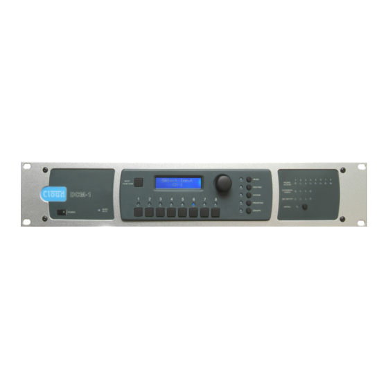
Cloud DCM-1 Руководство - Страница 3
Просмотреть онлайн или скачать pdf Руководство для Смеситель Cloud DCM-1. Cloud DCM-1 7 страниц. Digitally controlled zone mixers

Key Features
•
8 stereo line inputs (1 balanced), with input level trims (via menu
system)
•
8 balanced line outputs (2 stereo + 6 mono)
•
Any source may be routed to any zone at any level
•
4 Extension Ports for optional remote line input modules
(balanced or unbalanced), using Cat 5 UTP cable
•
4 Mic Inputs for optional remote mic input modules, using
Cat 5 UTP cable
•
External inputs (mic or line) may be routed to any zone
•
RJ45 interface for Cloud PM Series digital paging microphones
•
Separate analogue paging mic input with standard short-to-
ground zone selection
•
Paging to all zones with fully programmable override logic
•
Supports up to 100 CDR-1 Remote Controls (optional), in any
wiring configuration, using Cat 5 UTP cable
•
Remote control of source, level, EQ and group enable via
CDR-1 plates
•
2 x 16 character LCD dot-matrix display (both DCM1/DCM1e
and CDR-1)
•
Four definable zone groups; groups have same selection options
as zones
•
Any line input may have priority in any zone; configurable per-
zone
•
Configurable source selection restriction, per-zone
•
Key-protected "Installer" mode (both DCM1/DCM1e and
CDR-1) prevents user access to configuration menus
•
Inputs, zones and groups can be named
System Example - Hotel/Large Restaurant (DCM1)
The system shown could typically be a hotel or large
restaurant, and illustrate how some of the DCM1's
many features may be used in practice:
•
The large area has two CDR-1 remote controls
in the same zone; typically, these might be adjacent to
doors at opposite ends of the room.
•
Two of the areas are separated by a folding partition
which may be removed to create one large space. By
assigning these two zones to a Group within the DCM1,
the two zones can be treated as one for audio purposes
when the partition is removed and return to two
separate zones when it is reinstated.
•
Each half of the partitioned area also has an ME-1
mic input plate. Because these have been wired back to
the DCM 1 independently, each can be made available
to their respective room halves as and when required.
Alternatively, it may be that they are only required
when the partition is folded back; in this case they are
activated for the Group instead.
•
If the model of mixer is a DCM1e, system control is
available to the user via a web browser on an Internet-
capable device. Browser control can be configured
at installation so that only the operational features
required by the venue staff are accessible to them; all
other functions are password-protected.
•
RS232 interface for control by third-party control systems
•
Paging access port may be reconfigured as eight GPIO ports,
under RS-232 or Ethernet (DCM1e only) control
•
Front-panel LEDs confirm remote access
•
Optional per-zone EQ cards to suit a range of popular installation
loudspeakers
•
Software Configuration Tool available (free download) to permit
easy configuration from a computer
•
Self-contained - can be fully configured and controlled without a
computer if preferred
•
Multiple mixers may be cascaded to create larger systems
•
External Music Mute input for interfacing with emergency
systems
•
Any input (mic or line) may be assigned as Emergency Input,
overriding Music Mute
•
2U 19" rack-mounting unit
DCM1e only – Additional features
•
Ethernet port with internal web server
•
Control over main user functions from web-capable devices
•
Extended range of password-protected functions
•
Ethernet to RS232 bridge may be used to send commands to
third-party equipment
CD
JUKEBOX
MUSIC
SERVER
INPUT 1
INPUT 2
INPUT 3
OFF-AIR
INPUT 4
RECEIVER
INPUT 5
INPUT 6
INPUT 7
MP3
INPUT 8
PLAYER
MIC 1
DOCK
MIC 2
MIC 3
MIC 4
PAGING MIC
PAGING ACCESS
CDPM
1
2
3
COMPUTER
4
OR TABLET
ETHERNET
Wireless Access Point
or Router for DCM1e
only.
C l e a r l y b e t t e r s o u n d
POWER
AMPLIFIERS
ZONE 1
ZONE 2
ZONE 3
ZONE 4
ZONE 5
ZONE 6
OTHER
ZONE 7
AREAS
ZONE 8
DCM1 or
DCM1e
AREAS 1 & 2
CDR-1
ME-1
PARTITION
CDR-1
ME-1
AREA 3
CDR-1
AREA 4
CDR-1
