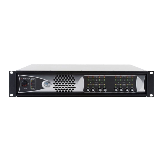
Operating Manual - NE Multi Channel Power Amplifier
Amplifier Rear Panel
1. Optional Cobranet Card CNM-2 – Installation of this option allows this amplifier to be part of a Cobranet
audio network.
2. Optional AES/EBU or MIC Input - This slot allows for installation of an AES/EBU digital input or MIC input.
3. Ethernet Port - This jack offers ethernet control and monitoring of basic amplifier functions using Protea
software.
4. Input Connector - This is used for a three wire (G, +, -) balanced input. Standard connectors are two-piece
euroblock, with XLR connectors optional equipment.
5. Normal/Bridge Switch - This switches the channel pair to Bridge Mode
6. Euroblock Speaker Connectors - Used to connect the speakers
7. Remote Standby - These two contact closure pins are wired to a switch to remotely place the amp in standby.
8. Preset Recall - These four pins (and GND) can be wired to remote contact closure switches to recall up to four
amplifier presets.
9. Data - These four pins can be wired to remote microprocessor based controllers such as the WR-5 or RD-8C.
10. Remote Level Control - These pins can be wired to remote potentiometers such as the WR-1 for level control
of individual channels
11. AC Inlet - Used for the detachable AC cord.
WARNING: Do not remove or lift the mains connector ground.
Installation
Before connecting to mains power, make sure that the switches and wiring are all set to the configuration needed for your
particular application. Failure to do so could result in damage to the unit or other components in your system. CAUTION:
When mounting or connecting the amplifier, always disconnect it from the mains. Use four screws and washers when mounting
the amplifier to the front rack rails. Rear support is also recommended, especially for mobile or touring use. To reduce the risk
of fire or electric shock, do not expose this apparatus to rain or moisture.
Requirements
NE-series multichannel amplifiers have specific physical, electrical and signal requirements for proper operation. These
requirements will vary depending on your specific application, setup, and the settings on the amplifier. When setting up and
testing your system, please take special care to double check all connections and settings. Please refer to the specifications sec-
tion of this manual for specific input, output and other figures.
Constant Voltage Models (25V, 70V, and 100V) and High Pass Filters
The 25V, 70V, and 100V amplifiers include internal, factory installed High Pass Filter hardware. This allows for software
selectable filters on each channel that prevent low frequency energy from saturating the core of low cost speaker tap transform-
ers. Available settings are 80Hz (12dB/oct), 400Hz (6dB/oct), and OFF. The 400Hz setting is commonly used in paging systems
with horn speakers. Note that with the HPF hardware installed, that amplifier can not have any of the optional AES/EBU input,
MIC input, or DSP hardware.
The DSP option can be factory installed in lieu of the HPF hardware, with HPF frequencies set in software to any value
from 20Hz to 20kHz with a slope of 12dB/oct to 48dB/oct and various response options. In order to have AES/EBU capability
in a constant voltage amplifier, the DSP option must be installed.
ne
7

