Ashly Protea NE8250 Руководство по эксплуатации - Страница 7

Просмотреть онлайн или скачать pdf Руководство по эксплуатации для Компьютерное оборудование Ashly Protea NE8250. Ashly Protea NE8250 8 страниц. Network enabled multi-channel power amplifiers
Также для Ashly Protea NE8250: Руководство по эксплуатации (16 страниц), Руководство по эксплуатации (16 страниц), Технические характеристики (2 страниц), Технический паспорт (2 страниц), Руководство по эксплуатации (16 страниц), Руководство по эксплуатации (16 страниц), Руководство по эксплуатации (20 страниц)
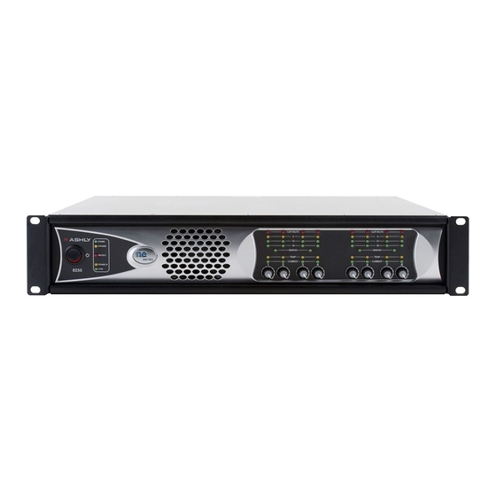
Ashly Protea NE8250 Руководство по эксплуатации
Input Connectors- removable euroblock connectors for balanced analog audio signal input.
The Input Connectors are not used in the ASTi system setup.
3.3

Front Panel Connections

Channel Level Controls- act as the overall master gain control for each channel. The exact set-
ting required for any specific installation will depend on a number of factors including speaker
placement, speaker sensitivity, size of the space being driven, and of course the required sound
level required from the system. Conventional audio set-up procedures apply, such that the
signal source should be set to the maximum level achievable while avoiding overload (clipping)
for the loudest signal levels required from the system (typically the "crash" sound for a flight
simulator), this affording the maximum signal-to-noise performance, and then setting the am-
plifier Channel Level Controls to achieve the required loudness for this particular sound. In
normal use, the Telestra configuration service will disable these controls.
4
Technical Specifications
4.1

Wiring

Select the appropriate size of the wire based on the distance from the amplifier to the speaker.
Warning: Never connect the speaker return to the chassis of the amplifier or damage to the
amplifier may result. Never use shielded cable for output wiring.
4.2

Minimum Guaranteed Power

- 150W per channel @ 8 Ohms
- 250W per channel @ 4 Ohms
4.3

Memory Devices

The Ashly Amp memory devices are summarized in the table below.
Distance
up to 25 ft. (7.6 m)
26–40 ft. (7.9–12.2 m)
41–60 ft. (12.5–18.3 m)
Over 60 ft. (18.3 m)
Volatile
MCU Internal Flash
MCU Internal SRAM
6
Wire Size
16 AWG
14 AWG
12 AWG
10 AWG
512kb
64kb