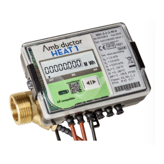
Ambiductor HEAT 1 Руководство по эксплуатации и монтажу - Страница 2
Просмотреть онлайн или скачать pdf Руководство по эксплуатации и монтажу для Измерительные приборы Ambiductor HEAT 1. Ambiductor HEAT 1 20 страниц.

General information
Energy measurement of heat and/or cooling for both the pri-
mary side of district heating and distribution measurement on
the secondary side. Certified according to MID for billing.
It is approved for billing the energy consumption in local or
district heating systems: in residential buildings, office build-
ings or energy plants and the like.
The meter can be mounted in both the forward and return
pipes (with the correct programming).
The meter comes with paired temperature sensors, pre-
installed at the factory. The user can also use other paired
temperature sensors that meet the requirements of Directive
2004/22/EC on metering instruments on March 31, 2004 and
which have type approval.
The heat meter meet the basic requirements of the Techni-
cal Regulation Measuring Instruments, dated March 30, 2006
(transposition into the NB Directive 2004/22 / EC of 31 March
2004 on measuring instruments):
Appendix I Basic requirements
Appendix MI-004 Thermal heat meter,
HEAT 1 complies with the European standard EN 1434 "Ther-
mal heat meter" parts 1 + 6.
HEAT 1 complies with the "C" class environmental protection
requirements according to EN1434-1: 2007
Ambient temperature: from +5° C to 55°C,
Mechanical environmental class: M1,
Electromagnetic environmental class: E2.
NOTE! The meter is a precision instrument and must be
treated as such during installation. Faulty handling can lead
to termination of the warranty. Use brass couplings to connect
the meter.
Principle of operation
The flow measurement is based on the ultrasound measure-
ment method. The ultrasonic signal in the flow directions
moves many times faster than against the flow. The ultrasonic
sensors must perform both transmitter and receiver functions.
From the resulting time difference, the flow rate is calculated.
The liquid temperature is measured with standard platinum
resistance temperature sensor Pt500. Paired temperature sen-
sors with 2-wire connection for measuring temperatures in the
supply and return pipes are used. Flow and return temperature
sensors can only be replaced in pairs.
Energy Calculation Formulas:
Flow sensor in supply line
Q = V1 * ρ1 * (h
-h
)
T1
T2
Flow sensor in the return line
Q = V1 * ρ2 * (h
-h
)
T1
T2
Explanation of abbreviations:
Q = thermal energy
V1 = Water volume, m3
ρ1 ρ2 = Water densities, according to supply and return water tempera-
tures Θ1, Θ2
h
, h
- Enthalpies, according to water temperatures Θ1, Θ2
T1
T2
When the cooling function is activated by reversed tempera-
ture difference, the cooling energy will be registered in the
extra register:
Σ Q = Q1 + Q2
Flow sensor in flow line
When Θ1> Θ2: Q1 = V1 * ρ1 * (h
When Θ1 <Θ2: Q2 = V1 * ρ1 * (h
Flow sensor in return line
When Θ1> Θ2: Q1 = V1 * ρ2 * (hT1-hT2); Q2 = 0
When Θ1 <Θ2: Q2 = V1 * ρ2 * (hT2-hT1); Q1 = 0
The Integration Agency performs all necessary measuring and
data storage functions.
Ambiductor AB reserves the right to make changes without prior notice. Reprinting or copying this publication without permission is prosecuted.
-h
); Q2 = 0
T1
T2
-hT1); Q1 = 0
T2
Security
The meter is powered from the battery (3.6 V) or 230V.
During the installation and service of the meter, heat-bearing
fluid can flow through the flow sensor with static pressure up
to 1.6 MPa and temperatures up to 180 °C.
Only qualified technical personnel can install and maintain
heat meters. Staff must be familiar with appropriate techni-
cal documents and general safety regulations. It is necessary
to observe the general safety requirements during installation
and maintenance process.
Unit meets safety class II. Protective grounding is not re-
quired, since the casing is made of plastic, and the conductive
parts are not exposed to the surface. Safety guarantees when
installing and servicing the meter are:
•
Reliable electrical circuit insulation,
•
Hermetic installation of the primary flow and tempera-
ture sensor in the pipeline,
•
Reliable attachment of sub-units by heat meters during
installation. Safety requirements for temperature sensors
can be found in the appropriate technical documentation.
Warning! Mounting of the different parts of the meter is
only permitted after ensuring the absence of heat-bear-
ing fluid in the pipeline.
NOTE! Work with high-voltage circuits may only be done by
authorized personnel.
NOTE! Work with pipe systems may only be done by autho-
rized personnel.
Warranty
The manufacturer guarantee that the equipment meets the
stated technical requirements, provided that transport, storage
and operating conditions are followed.
Transport and storage
Requirements for safe transport and storage regarding tem-
perature, pressure and humidity can be found in Technical data
below.
Packed equipment may be transported in all types of covered
vehicles. Equipment must be anchored in a reliable manner to
avoid shocks etc.
Equipment must be protected against mechanical damage and
shock.
Equipment must be stored dry in heated rooms, where the
ambient temperature is not less than + 5 °C. No aggressive
chemical substances should be stored together due to risk of
corrosion.
2
