ambiq micro Apollo4 Blue Plus Краткое руководство по эксплуатации - Страница 10
Просмотреть онлайн или скачать pdf Краткое руководство по эксплуатации для Одноплатные компьютеры ambiq micro Apollo4 Blue Plus. ambiq micro Apollo4 Blue Plus 19 страниц.

5.
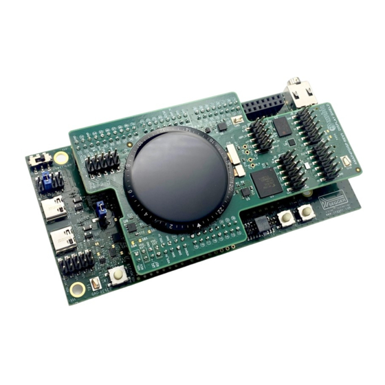
Overview of the Apollo4 Display Kit
The Apollo4 Plus Display Kit consists of two PCB assemblies:
1.
The Apollo4 Plus EVB (AMAP4PEVB), revision 2 or later
2.
The Apollo4 Plus Display Shield revision 1
Please note that the Apollo4 Plus Display Kit is only compatible with the (non-blue) Apollo4 Plus EVB, part
number AMAP4PEVB.
The combined features of the two-board assembly are shown in the block diagrams of Figure 2 and
Figure 3. When MSPI0 is used in hex mode (16-bit interface), MSPI1 cannot be used, as the MSPI0 upper
data lines use the same pins on the Apollo4 Plus that MSPI1 uses. An Apollo4 Plus GPIO pin, GPIO34, is
used to select between using this set of pins as MSPI1 connections or as the upper data lines of MSPI0 in
hex mode.
Figure 2 represents the two-board assembly's feature set when connected to the APS256XXN PSRAM
device over MSPI0 in hex mode. MSPI1 is not used in this configuration.
Apollo4
Plus
Display
Shield
Figure 2. Apollo4 Plus Display Kit Block Diagram - MSPI0 Hex to PSRAM Only
QS-A4PDK-1p0
Apollo4 Plus Display Kit Quick Start Guide
APS256XXN
PSRAM
454*454
AMOLED
Display
THGBMNG5D1LBAIT
e-MMC
ADXL362
Accel
Page 10
EVB Headers
Hex-MSPI0
MSPI1
not used
MIPI DSI
Quad-MSPI2
I2C
Apollo4
Touch
ALS
Plus
EVB
SDIF
SPI
J-Link
Debugger
USB
User LEDs
Power
Headers
Audio Jack
Debug
In/Out
Connectors
MCU USB
Connector
2022 Ambiq Micro, Inc.
All rights reserved.
