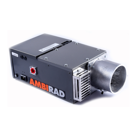
Ambirad AR45/50' SL Kurulum ve Servis Kılavuzu - Sayfa 19
Gazlı Isıtıcı Ambirad AR45/50' SL için çevrimiçi göz atın veya pdf Kurulum ve Servis Kılavuzu indirin. Ambirad AR45/50' SL 20 sayfaları. Gas fired radiant tube heaters

- 1. Table of Contents
- 2. AR and ARE Series Gas Fired
- 3. Gas Connection
- 4. Standards
- 5. Assembly Instructions
- 6. Fitting Reflectors and End Caps
- 7. Burner/Fan/Damper Assembly
- 8. AR and ARE Series Double Linear
- 9. HB and DL Damper Settings
- 9. Installation – Suggested Methods
- 9. Of Heater Suspension
- 10. Flue Connection
- 11. Commissioning for Individually
- 12. Routine Service
- 13. Trouble Shooting Checklist
- 14. User Instructions for Ambi-Rad
18 Trouble shooting checklist
Symptoms
Burner will not start
Red 'mains on' does not illuminate.
Red light illuminates.
HB Herringbone system only.
Fan starts but burner does not attempt
ignition.
HB Herringbone system only.
Burner proceeds to ignition stage (normally
indicated by audible spark valve energised
and 'burner on' light illuminated) but burner
does not light.
Burner lights but shuts down after
a few seconds.
Heater shuts down after operating
for a period of time.
Possible causes
External controls, thermostats, time switch etc.
not calling for heat.
Fuse blown.
Fan's connector plug not fully engaged.
Loose electrical connection.
Fan seized or faulty motor.
Sequence controller relay failing
to pull in and/or hold in.
Vacuum switch not returning to normal
(switch off) position.
Fan tripped out on overload. (Type O fans only)
Insufficient vacuum generated by fan.
Blocked emitter tube.
Combustion chamber cover permitting
air leakage.
Vacuum impulse line between combustion
chamber and vacuum switch insecure
or defective.
Vacuum switch 'pulls in' but electronic sequence Replace burner sequence controller unit but
controller does not proceed to programme
ignition sequence.
Leaks in joint separation in manifold system.
No spark.
Gas safety valve faulty or defective.
Insufficient gas pressure.
Inadequate flame signal. This can be verified
by connecting a sensitive micrometer in
series with the violet wire which passes through
the combustion chamber bulkhead. The correct
reading should be 5µA ± 1µA.
Flame unstable.
Inadequate gas supply. Observe burner
gas pressure with all heaters operating.
Insufficient vacuum at combustion chamber
causing vacuum switch to cut off.
Refer to above.
Remedy
Adjust controls.
Check for short circuit in wiring
or individual electrical components.
Engage securely.
Check all connections.
Replace fan, recommission heater,
checking gas pressure settings.
Check vacuum switch is satisfactory,
replace sequence controller.
Replace vacuum switch.
Check overload setting: single phase
3.1 amp. Reset button on in control panel.
Check for build up of condensate in fan casing.
Clean fan blades with soft bristle.
Clean emitter tube internally.
Examine condition of sealing gasket, tighten
down lid securely.
Fix securely in place.
first check that the cause of failure is not a
short on output circuit, by measuring resistance
between pins 2 and 7 of burner control unit
plug. A reading of 10,000 ohms indicates short
circuit on gas valve burner indicator light or
associated wiring.
Reseal or reconnect.
Check electrode for cracks – replace if necessary.
Check high tension connections are secure.
Check spark gap is 3.5 ± 0.5mm. If no high
tension output from electronic controller,
replace controller.
Replace solenoid operator section of gas valve.
Set burner pressure to that indicated on data
badge (see commissioning).
Replace electrode. Check connections to
electrodes and terminal 4 of electric sequence
controller plug. Replace the electronic
sequence controller.
Check cleanliness of burner and set burner
pressure as indicated on data badge.
If gas pressure drops below that indicated on
the data badge, examine gas supply pipework
for excessive pressure loss.
Clean fan blades with soft bristle brush.
Inspect tube internally and clean if necessary
(see servicing instructions).
If problem persists, replace vacuum switch.
19
