AMC AMP 1500 Kullanıcı Kılavuzu - Sayfa 7
Amplifikatör AMC AMP 1500 için çevrimiçi göz atın veya pdf Kullanıcı Kılavuzu indirin. AMC AMP 1500 8 sayfaları. Power amplifier

Operation
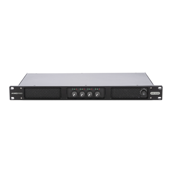
Front panel functions
VOLUME CONTROLS
Rotary knobs for adjusting the volume level of the selected channel.
LED INDICATORS
The power LED indicator illuminates when the power is turned "ON".
The signal LED indicator illuminates when the input signal is greater than
-14 dBu is present.
The clip LED indicator when the input signal is greater than +3 dBu is present.
Occasional blinking is acceptable, but if LED lights on more than intermittently,
turn down either the power amplifier level or reduce the output level of the
preceding component to avoid audible distortion.
POWER SWITCH
Switch amplifier power ON or OFF.
Rear panel functions
MAINS POWER CONNECTOR
Power connector for mains power.
AMPLIFIER OUTPUT CONNECTORS
Audio outputs designed to connect speakers by using Speakon type connector.
AMPLIFIER INPUT CONNECTORS
Input connector designed to connect external audio signals.
AMPLIFIER LINK CONNECTORS
Connect outgoing audio signal from input connectors to additional amplifier.
Input and link connectors are connected with each other directly.
OPERATION MODES
There are 3 available modes of operation: stereo, bridge, and parallel. Turn off
the amplifier before switching these modes.
Stereo mode: This is a general mode. In this mode all amplifier channels are
separate from each other and can be used individually. All inputs require an audio
signal and all volume controls are active. The minimum loudspeaker impedance is
specified in the general specification table on the user manual's last page.
Bridge mode: This mode combines power from two channels to drive a single
loudspeaker. If bridge mode is activated the audio signal to AMP 500 and
AMP 1500 amplifiers should be connected to Input1. Connect audio to Input3
to bridge 2 and 3 AMP 4X500 amplifiers' outputs. The minimum loudspeaker
impedance should be 4 Ω for AMP 500 and AMP 1500 models and 8 Ω for AMP
4X500 model. Before enabling Bridge mode pay attention to the wiring diagram
on the rear panel of the amplifier. Bridge mode requires specific wiring.
Parallel mode: This mode allows to operation of two amplifier channels in parallel
with the same audio signal. Two inputs are internally connected, so only Input1
and Input3 require an audio signal for the AMP4X500 amplifier. Use Input1 only
for two-channel amplifiers AMP 500 and AMP 1500. In parallel mode all volume
controls are active. Do not use parallel mode then feed the amplifier with separate
audio signals. Please note that only amplifier inputs are connected in parallel. Do
not connect output connectors in parallel! This is not an output parallel mode.
USER MANUAL
AMP Power Amplifier
07
