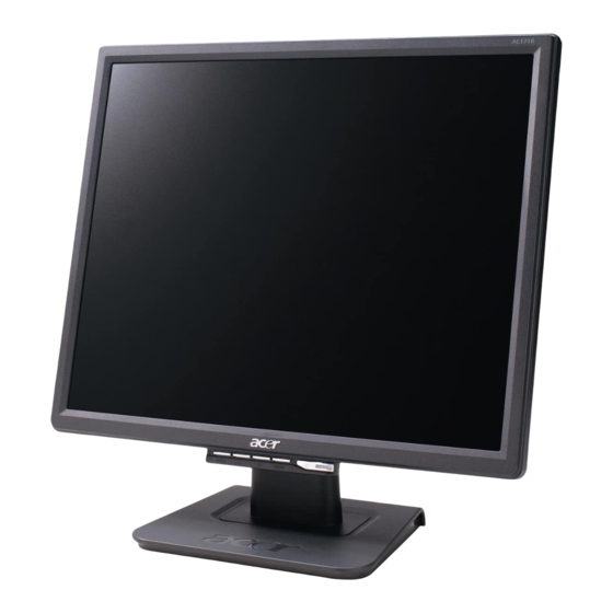
Acer AL1716as Servis Kılavuzu - Sayfa 27
Monitör Acer AL1716as için çevrimiçi göz atın veya pdf Servis Kılavuzu indirin. Acer AL1716as 50 sayfaları.

MACHINE ASSEMBLY
This chapter contains step-by-step procedures on how to assemble the monitor for maintenance
and troubleshooting.
NOTE:
1. The screws for the different components vary in size. During the disassembly process, collect the screws with the
corresponding components to avoid mismatch when putting back the components.
2. The monitor surface is susceptible to scratching! Therefore, lay the monitor on a soft surface when mounting or
removing the base.
3. Wear gloves
Chassis*1
PCBA Power Board *1
INSULATOR PC,MYLAR
SCREW (PW 3*6,M,ZN) *3
PCBA I/F BOARD *1
CABLE 30P FFC
HRN ASS'Y 8P
SCREW (PW 3*6,M,ZN) *3
PCBA Control Board *1
SCREW (PW 3*4,M,ZN)
*2
INL Panel*1
SCREW (PW3x4,M,ZN)*4
FFC(30pin)*1
TAPE,ACE#LP1701(40x20mm)*1
INSULATOR PC#LE1710
Insert B/L jack*4
EMI shield Tape*2
Back cover*1
Arm Stand*1
(M4x10,ZN)*4
Bracket Finger
*1
27
Chapter 3
Stand plate*1
Rubber*4
Hinge cover*1
Front bezel*1
Button*1
Indicator*1
