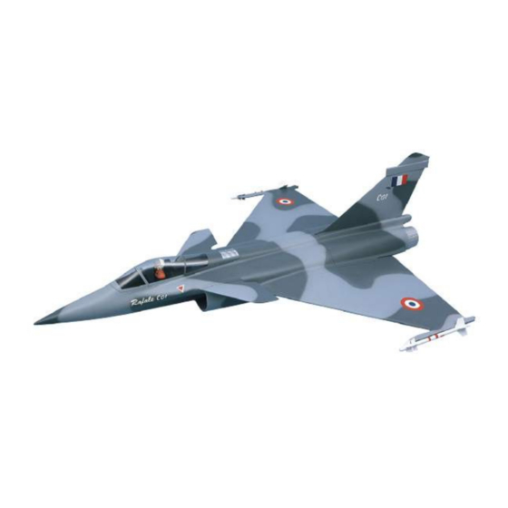
aero-naut Dassault Breguet Rafale C 01 1358/00 İnşaat Talimatları - Sayfa 3
Oyuncak aero-naut Dassault Breguet Rafale C 01 1358/00 için çevrimiçi göz atın veya pdf İnşaat Talimatları indirin. aero-naut Dassault Breguet Rafale C 01 1358/00 8 sayfaları.

Dassault Breguet Rafale C01
through the noseleg steering arm, then fit the
tubular rivets on them (D). Pull the cables taut
with a pair of pliers, and solder them to the
C
tubular rivets.
D
4) Nosewheel door actuator
C
D
Glue one end of a length of steel cable (A) to the
centre of the nosewheel door, and the other end
74
to the inside of the fuselage on the opposite side.
Set the cable length so that the wheel door is
pulled up by the undercarriage leg when the
nosewheel is retracted.
5) Main retract unit hinges
The main wheel doors are attached to the fuselage (1) using two hinges (59) each. Note that
small notches must be cut in the fuselage and the wheel door, so that the axis of the hinge
pivots lines up with the cut edge of the wheel door opening.
Glue the main (rear) undercarriage hinges (59) to the fuselage, then tape the wheel doors to
the fuselage and glue the hinges to the doors from the inside. Allow the glue to set hard, then
apply a patch of glass cloth over the top using epoxy. Please take care to avoid resin running
into the hinges.
A
6) Main undercarriage former assembly
The support for the main undercarriage is assembled from parts (60 - 66) as shown in the
drawing; tack the joints temporarily using cyano.
The holes for the retract unit retaining screws in parts (62 + 63) must be drilled accurately.
Check the hole positions by offering up the retract units before gluing the parts in place.
The nuts for the retract unit retaining screws must be glued in place at
this stage. Place the former assembly in the fuselage and align the rear
61
face of the former (60) with the front edge of the wheel door opening.
Check that the retract units work correctly, with proper clearance. When
you are confident of this, apply more cyano to the former assembly to
62
63
64
reinforce the joints. Allow the glue to cure fully, then glue the former
63
62
64
assembly in the fuselage. Reinforce the joints between the formers and
the fuselage with additional rovings.
7) Air ducts
Remove 5 mm from the outer side of the front face of the air ducts (70),
60
leaving a projecting flange which can be glued to the inside of the
fuselage. At the rear end of the ducts, where the impeller unit fits, cut back the centre area as far as the shoulder,
and cut a circular recess in the connecting walls to clear the rotor hub. This will ensure that the ducted fan unit
can be slid into the two air ducts as far as it will go.
Fit the air intake ducts (70) in the fuselage through the main undercarriage support former assembly (60 + 61),
and position them flush with the cut-outs in the air intake at the front. Glue the air ducts to the inside of the
fuselage by means of the projecting 5 mm flange, and apply glass tape over the joint.
8) Ducted fan unit
Fit the motor bulkhead (68) in the fuselage, and fit the air ducts (70) through it. The
air ducts (70) must end flush with the bulkhead (68).
Slide the ducted fan unit into the air ducts (70) as far as it will go, push the GRP
ring over the unit until it rests against the motor bulkhead, and tack it lightly to the
ducted fan unit using cyano. Mark the retaining screw holes on the motor bulkhead
70
(68). Withdraw the ducted fan unit from the air ducts, and reinforce the joint
between the GRP ring and the ducted fan unit. Drill the holes in the motor bulkhead
for the fan unit retaining screws, attach the impeller unit to the motor bulkhead (68)
and glue the nuts securely to the bulkhead (68).
61
Glue the motor bulkhead (68) in the fuselage, flush with the end of the
air ducts; reinforce the joints with additional rovings. The central
66
connecting walls of the air ducts must now be glued together.
9) Air intake lips
Cut back the edge of the air intake lips (5) on both sides, as shown in
60
the picture; they are supplied already trimmed to the correct width of 10
mm. The intake lips can now be glued to the outside recess in the
fuselage (1) and the inside of the air duct (70).
65
3
Building instructions - Rafale C 01 - Aramid
