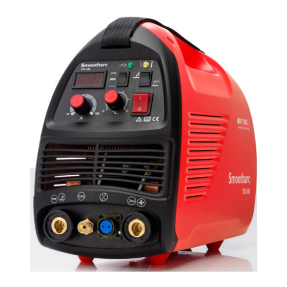
BOC Smootharc TIG 185 DC Servis Kılavuzu - Sayfa 5
Kaynak Sistemi BOC Smootharc TIG 185 DC için çevrimiçi göz atın veya pdf Servis Kılavuzu indirin. BOC Smootharc TIG 185 DC 19 sayfaları. Boc smootharc tig 185 dc welder
Ayrıca BOC Smootharc TIG 185 DC için: Kullanım Kılavuzu (15 sayfalar)

Ver.1 Rev.1 . 0314
1.2
First rectifier board schematic
Ser. No. Pin
Description
CON1
1
Under gas delay, the output is 24V when TIG
works
2
Control works the signal, output the high
frequency when TIG
3
GND
4
DC24V
CON2
1
Pin 1 and Pin 2 is short frequency when TIG
2
works circuit, output high
CON3
1
2T°XHigh frequency 12V°A4T---Low frequency 0V
2
DC12V
CON4
1
Connect to ground by PTC-12
2
NC
3
High frequency
CON5
1
Pin 1 and Pin 3 connect to the TIG torch, Pin 2
2
and Pin 3 connect to the MMA torch
3
4
NC
CON6
1
GND
2
The rated voltage is adjustable
3
Provide power supply to the potentiometer
CON7
1
GND
2
Current feedback
3
Voltage feedback
CON8
1
Connect to the attenuation potentiometer
2
3
When connect to Pin4, It is low voltage
4
GND
5
When connect to Pin4, it is middle voltage
CON9
1
Connect to the thermal switch, connect to the
ground when over-heat works
2
GND
BOC Smootharc TIG 185 DC Service manual
Ser. No. Pin
Description
CON10
1
DC24V
2
This port connect to the over-heat indicator
CON11
1
GND
2
Connect to the power indicator, this pin is high
voltage
CON12
1
GND
2
GND
3
DC5V
4
The signal terminal of the digital meter
CON13
NC
CON14
1
GND
2
GND
3
GND
4
NC
5
DC340V
6
DC340V
7
DC340V
CON15
1
Pin 1 and Pin 3 output AC wave(+340V and
-340V)
2
NC
3
Pin 1 and Pin 3 output AC wave(+340V and
-340V)
CON16
1
Inverter AC output
2
Inverter AC output
3
Inverter AC output
4
NC
5
Inverter AC output
6
Inverter AC output
7
Inverter AC output
CON17
1
Low voltage
2
The signal terminal of the digital meter
3
The power terminal of the digital meter
5
