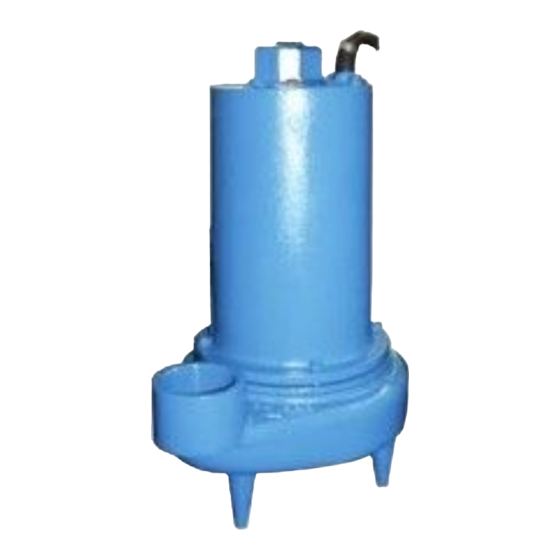
Barnes 3SE-DS Series Kurulum ve Kullanım Kılavuzu - Sayfa 9
Endüstriyel Ekipmanlar Barnes 3SE-DS Series için çevrimiçi göz atın veya pdf Kurulum ve Kullanım Kılavuzu indirin. Barnes 3SE-DS Series 18 sayfaları. Submersible sewage ejector
Ayrıca Barnes 3SE-DS Series için: Kurulum ve Kullanım Kılavuzu (17 sayfalar), Kurulum ve Kullanım Kılavuzu (20 sayfalar)

Important ! - ALL parts must be clean before
reassembly.
F-3.2) Reassembly:
Bearing - When replacing bearing, be careful not to damage
the rotor or shaft threads. Clean the shaft thoroughly.
Insert retaining ring (29) onto motor shaft. Apply adhesive
compound to the shaft and press bearing (39) on the motor
shaft, position squarely onto the shaft applying force to the
inner race of the bearing only, until bearing seats against
retaining ring (29).
Motor - Slide lower bearing (39) and motor rotor squarely into
the bearing bracket (20) until bearing seats on the bottom.
Insert retaining ring (28) into bearing bracket (20).
SINGLE PHASE, 230 VOLT AC
Power Cable (9a)
Motor Lead Number
Green (Ground)
Green
Black
1
White
2
Flag Terminal
Capacitor
Flag Terminal
Capacitor
THREE PHASE, 200/230 VOLT AC
Power Cable (9a)
Motor Lead Number
Green (Ground)
Green
Black
1 & 7
Red
2 & 8
White
3 & 9
4, 5 & 6 Together
THREE PHASE, 460/575 VOLT AC
Power Cable (9a)
Motor Lead Number
Green (Ground)
Green
Black
1
Red
2
White
3
4 & 7 Together
5 & 8 Together
6 & 9 Together
All manuals and user guides at all-guides.com
Position motor housing and stator into pilot, aligning holes
in bearing bracket (20). Apply thread locking compound on
motor bolts and tighten. Torque motor bolts to 17 ft. lbs. Place
all motor leads above the motor. Position square ring (36) on
bearing bracket (20) and lower housing (2) over motor and
into pilot. Make wire connections per paragraph F-3.3.
F-3.3) Wiring Connections:
Check power cable (9A) and control cable (9E) (if used), on
conduit box (9),for cracks or damage and replace complete
conduit box assembly (9) if required (see Fig. 4). Bring motor
wires through wire opening in top of housing (2), position
square ring (10) in conduit housing (9) and reconnect motor
leads to power cable and moisture and temperature sensor
leads to control cable (if equipped) using connectors (11) and
(16) as show in Fig. 3.
FIGURE 3
9
CONNECTORS
CONNECTORS
CONNECTORS
CONNECTORS
