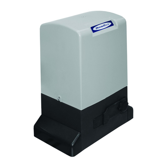
DoorHan SLIDING-1300 Kurulum ve Kullanım Kılavuzu - Sayfa 10
Kapı Açıcı DoorHan SLIDING-1300 için çevrimiçi göz atın veya pdf Kurulum ve Kullanım Kılavuzu indirin. DoorHan SLIDING-1300 16 sayfaları. Drive
Ayrıca DoorHan SLIDING-1300 için: Kurulum ve Kullanım Kılavuzu (12 sayfalar), Kurulum ve Kullanım Kılavuzu (12 sayfalar)

5. Photo op — contacts for connection of opening safety devices (NC). Actuation of the devices causes immediate stop.
Actuation of the devices connected to these terminals does not effect the operation when the door closes. If the door is closed
and sensors connected to these terminals actuated, the door will not open. To connect several devices with NC contacts, connect
then in series.
note! If no devices are connected to these terminals, place a jumper between the contact terminals Ph op and — (see the
electric diagram).
6. eMRG — contacts for connection of emergency stop devices (NC). These connections are used to protect the door leaf
when it opens and closes. Any operational logic of the control unit enables immediate stop of the door after the signal from these
devices. If the door does not move and the sensors connected to these terminals actuated, the door will not move. To connect
several devices with NC contacts, connect them in series.
note! If no devices are connected to these terminals, place a jumper between the contact terminals eMRG (see the electric
diagram).
7. 24 V DC — output terminals on power supply transformer 24 V DC max load 600 mA.
AttentIon! If you change position of DIp switches or mechanical regulators, turn off and then turn on again
the supply voltage of the operator. Otherwise the changes made will not take effect.
5.2. DIP switches
Dip1 — operation mode. If Dip1 is off, the Start command will be not taken when the door opens (on/off).
Dip2 — separate control. If Dip2 is on, separate control can be realized. The device connected to the Start terminal sends an
open command and the device connected to ped terminal sends a close command (on/off).
Dip3 — operator's opening direction. If Dip3 is on, the operator is on the right of the aperture. If Dip3 is off, the operator is on
the left of the aperture.
Dip4 — limit switch (Dip4 on/off — NO/NC).
Adjustment of DIP-switches
If you change position of DIp switches or mechanical regulators, turn off and then turn on the power of the operator. Otherwise
the changes made will not take effect.
Operation mode. Stops the gate movement after the START command is sent
Dip1
Dip2
Separate control:
START — opens the gate, pED — closes the gate
Dip3
position of the operator relative to the gate
Type of limit switch contacts
Dip4
5.3. Mechanical regulators
tIMeR W — adjustment of the motor running time. It's used as a backup safety device. pause time is adjusted within the
interval of 0–100 sec. Extreme right position of the pointer corresponds to the maximal running time.
AUto Cl — adjustment of pause time before automatic closing of the door. pause time is adjusted within the interval of
0–70 sec. Automatic close function is off if the regulator is in the end left position.
FoRCe — operator's pulling force adjustment (setting of maximal consumption current). If the regulator is in the end right
position, the operator force is maximal (not recommended).
10
electrIcal cOnnectIOns
No
ON
Yes
OFF
No
ON
Yes
OFF
To the right
ON
To the left
OFF
NO
ON
NC
OFF
