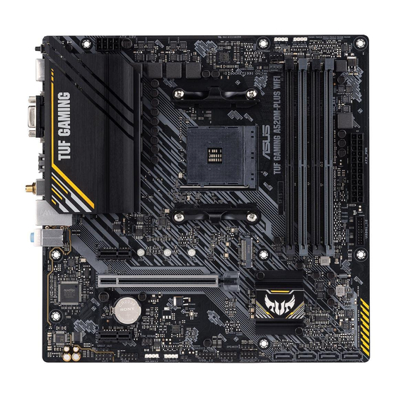
Asus 90MB14Y0-M0EAY0 Manuel - Sayfa 11
Anakart Asus 90MB14Y0-M0EAY0 için çevrimiçi göz atın veya pdf Manuel indirin. Asus 90MB14Y0-M0EAY0 30 sayfaları.

8. USB 3.2 Gen 1 header
The USB 3.2 Gen 1 header allows you to connect a USB 3.2 Gen
1 module for additional USB 3.2 Gen 1 ports. The USB 3.2 Gen 1
header provides data transfer speeds of up to 5 Gb/s.
The USB 3.2 Gen 1 module is purchased separately.
9. USB 2.0 headers
The two USB 2.0 headers allow you to connect USB modules for additional three USB 2.0
ports. The USB 2.0 headers provide data transfer speeds of up to
480 Mb/s.
DO NOT connect a 1394 cable to the USB connectors. Doing
so will damage the motherboard!
The USB 2.0 module is purchased separately.
10. Aura RGB header
The RGB header allows you to connect a RGB LED strip.
The RGB header supports a 5050 RGB multi-color LED strip
(12V/G/R/B), with a maximum power rating of 3A (12V), and no
longer than 3 m.
Before you install or remove any component, ensure that the ATX power supply is switched
off or the power cord is detached from the power supply. Failure to do so may cause severe
damage to the motherboard, peripherals, or components.
•
Actual lighting and color will vary with LED strip.
•
If your LED strip does not light up, check if the RGB LED extension cable and the
RGB LED strip are connected in the correct orientation, and the 12V connector is
aligned with the 12V header on the motherboard.
•
The LED strip will only light up when the system is powered on.
•
The LED strip is purchased separately.
11. Clear CMOS header
This header allows you to clear the CMOS RTC RAM data of the system setup information
such as date, time, and system passwords.
To erase the RTC RAM:
1.
Turn OFF the computer and unplug the power cord.
2.
Use a metal object such as a screwdriver to short the two pins.
3.
Plug the power cord and turn ON the computer.
4.
Hold down the <Del> key during the boot process and enter BIOS
setup to re-enter data.
If the steps above do not help, remove the onboard battery and short the two pins again to
clear the CMOS RTC RAM data. After clearing the CMOS, reinstall the battery.
ASUS TUF GAMING A520M-PLUS
PIN 1
USB3+5V
USB3+5V
IntA_P1_SSRX-
IntA_P2_SSRX-
IntA_P1_SSRX+
IntA_P2_SSRX+
GND
GND
IntA_P1_SSTX-
IntA_P2_SSTX-
IntA_P1_SSTX+
IntA_P2_SSTX+
GND
GND
IntA_P1_D-
IntA_P2_D-
IntA_P1_D+
IntA_P2_D+
GND
USB3
PIN 1
PIN 1
CLRTC
PIN 1
1-3
