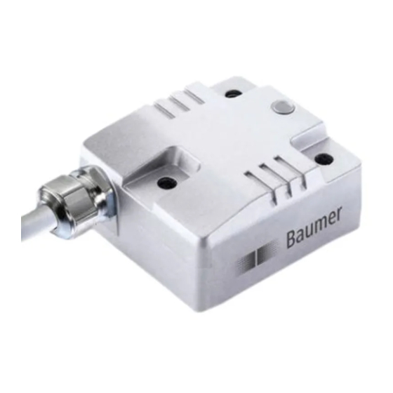
Baumer GIM500R Manuel - Sayfa 5
Aksesuarlar Baumer GIM500R için çevrimiçi göz atın veya pdf Manuel indirin. Baumer GIM500R 29 sayfaları. Inclination sensors
Ayrıca Baumer GIM500R için: Manuel (20 sayfalar), Manuel (13 sayfalar), Montaj Talimatları (2 sayfalar)

3
CAN-bus and CANopen communication
CAN bus (CAN: Controller Area Network) was developed by Bosch and Intel for high-speed, economic data
transmission in automotive applications. Today CAN bus has been commercialized for use in industrial
automation.
CAN bus is a fieldbus system (standards administered by CAN in Automation, CiA) for communication
between appliances, actors and sensors of different brands.
CAN-bus characteristics
3.1
• Data rate of 1 MBaud with network expansion up to 40 m
• Network connected on both sides
• The bus medium is a twisted-pair cable
• Real time capability: Defined maximum waiting time for high-priority messages.
• Theoretically 127 users at one bus, but physically only 32 are possible (due to the driver).
• Ensures data consistency across the network. Damaged messages are notified as faulty for all network
nodes.
• Message-oriented communication
The message is identified by a message identifier. All network nodes use the identifier to test whether the
message is of relevance for them.
• Broadcasting, multicasting
All network nodes receive each message simultaneously. Synchronization is therefore possible.
• Multimaster capability
Each user in the field bus is able to independently transmit and receive data without being dependent upon
the priority of the master. Each user is able to start its message when the bus is not occupied. When
messages are sent simultaneously, the user with the highest priority prevails.
• Prioritization of messages
The identifier defines the priority of the message. This ensures that important messages are transmitted
quickly via the bus.
• Residual error probability
Safety procedures in the network reduce the probability of an undiscovered faulty data transmission to
-11
below 10
. In practical terms, it is possible to ensure a 100% reliable transmission.
• Function monitoring
Localization of faulty or failed stations. The CAN protocol encompasses a network node monitoring
function. The function of network nodes which are faulty is restricted, or they are completely uncoupled
from the network.
• Data transmission with short error recovery time
By using several error detection mechanisms, falsified messages are detected to a high degree of
probability. If an error is detected, the message transmission is automatically repeated.
In the CAN Bus, several network users are connected by means of a bus cable. Each network user is able to
transmit and receive messages. The data between network users is serially transmitted.
Examples of network users for CAN bus devices are:
• Automation devices such as PLCs
• PCs
• Input and output modules
• Drive control systems
• Analysis devices, such as a CAN monitor
• Control and input devices as Human Machine Interfaces (HMI)
• Sensors and actuators
Baumer_GIM500R_CANopen_MA_EN.docx
03.19
5/29
www.baumer.com
