Baumer GNAMG Series Manuel - Sayfa 41
Aksesuarlar Baumer GNAMG Series için çevrimiçi göz atın veya pdf Manuel indirin. Baumer GNAMG Series 41 sayfaları. Inclination sensor with canopen interface
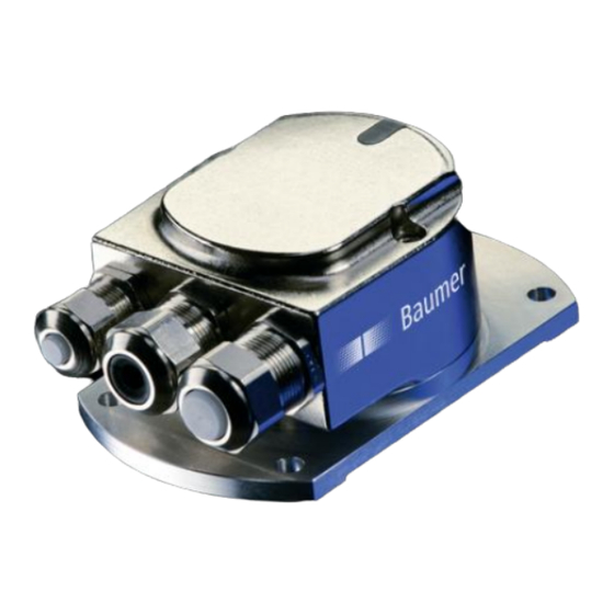
View inside the inclination sensor
Cable gland
6.2.5. Terminal assignment
Pin
Terminal
1
GND
2
UB
3
GND
4
CAN_H
5
CAN_L
Terminals with the same designation are connected to each other internally and identical in their functions.
Maximum load on the internal clamps UB-UB and GND-GND is 1 A each.
6.3. Status LEDs (status indicators)
An integrated DUO-LED is provided on the back of inclination sensor housing.
LED green
LED red
Off
Off
Flashing
Off
On
Off
On
On
Off
Flashing
Off
Off
Manual_GNAMG_CANopen_EN.doc
21.11.12
M12 connector
Explanation
Ground connection relating to UB
Supply voltage 10...30 VDC
Ground connection relating to UB
CAN Bus signal (dominant High)
CAN Bus signal (dominant Low)
Status
No supply voltage
Pre-operational Mode
Operational Mode
Stopped/Prepared Mode
Alert/warning
Error
41/41
M12-connector (male/female)
Baumer IVO GmbH & Co. KG
Villingen-Schwenningen, Germany