amphis 109001BB-24 Kurulum Kılavuzu - Sayfa 5
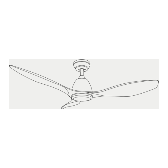
Fan amphis 109001BB-24 için çevrimiçi göz atın veya pdf Kurulum Kılavuzu indirin. amphis 109001BB-24 8 sayfaları. 3 blade ceiling fan

L U N A – I N S T A L L A T I O N M A N U A L
body) until the "Card Point" on the mounting bracket has dropped into the "Card Slot" on the
hanger ball and is firmly secure. (Fig. 6)
4 Connect electrical wires accurately according to the diagram. (Fig. 7)
5 After wires are connected, put the remote control receiver into the mounting bracket.(Fig. 8)
Input Wire L/Black
Input Wire N/White
Ground Wire /
Yellow & Green Wire
Remote Control Wiring Diagram
6 Raise up the canopy to the ceiling to cover the mounting bracket, making sure the canopy will
sit into the two screws on the mounting bracket. Then rotate the canopy to ensure the screw
heads are at the narrow end of the holes. (Fig. 9)
7 To attach fan blades, loosen and remove the six screws on the motor and set aside. Align the
two holes on the blade with the holes on the motor and secure the blade with two screws.
Repeat for the remaining blades. (Fig. 10)
8 Secure the lower cover to the thread at the bottom of the fan by twisting the nut clockwise
until firmly tight. (Fig.11)
Fig u re 9
Ground Wire /
Ground Wire /
Yellow & Green Wire
Yellow & Green Wire
Red Wire
Red Wire
Brown Wire
Brown Wire
Grey Wire
Grey Wire
Remote Control Receiver
Signal Reception Line
Remote Control Receiver
Fig u re 7
Fan Body
Fan Blade
Screws
Figu re 1 0
5
Figure 8
