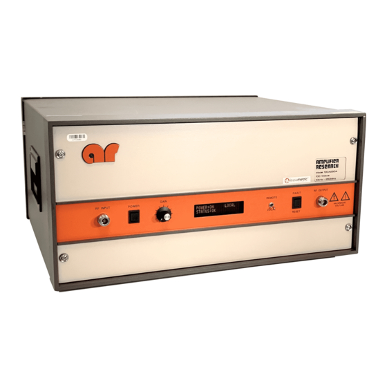
Amplifier Research 100A250 series Manuel - Sayfa 17
Amplifikatör Amplifier Research 100A250 series için çevrimiçi göz atın veya pdf Manuel indirin. Amplifier Research 100A250 series 19 sayfaları.

Model 100A250A
4.3.3 Thermal Fault (Schematic Diagram No 1010659) (continued)
4.3.3.1
fan (B1) is operating normally and that the air inlet on the bottom of the unit and the air outlets
on the rear of the unit are not blocked.
4.3.3.2
A4 Operate/Control Board, J3, Pin 21; it should be ≤0.1V.
4.3.3.3
ground.
4.3.4 Interlock Fault (Schematic Diagram No. 1010659)
The Model 100A250A is equipped with an interlock connector, which is located on the rear panel. The
interlock circuit can be used to sense the openings of doors to screen rooms, test chambers, and so forth,
and to turn off RF energy when these doors are opened.
Note: The Model 100A250A is shipped with a mating connector, which has a jumper between Pins
1 and 8, installed in the rear panel interlock connector. The unit will not operate unless the
interlock circuit is closed.
4.3.4.1
"INTERLOCK FAULT."
4.3.4.2
room, or are doors to the screen room open?
4.3.4.3
RESET switch.
4.3.4.4
(Pin 1 to Pin 8 in the connector, which mates with J2 in the rear panel).
4.3.4.5
4.3.4.6
Try to reset the unit; if the unit resets and operates normally, check to see that the cooling
If the unit does not reset and the cooling fan is operating normally, check the voltage at the
If the voltage on A4 J3, Pin 21 is high, check the thermal daisy chain through A2S1 to
In the event of an Interlock Fault, the unit's front panel VFD should indicate
Check to see if it is safe to power up the unit—are there personnel present in the screen
After checking for safety, try to clear the Interlock Fault from the front panel by using the
If the Interlock Fault will not clear, check for continuity in the External Interlock Circuit
Check the voltage on A4 J3, Pin 5; it should be ≤0.1V.
If all of the above voltages are correct and the unit still will not reset, check for defective
wiring and/or PWB connections, then try the RESET switch again. If the unit still will not
reset, the A4 Operate/Control Board is defective. Contact Amplifier Research to arrange
for repair or replacement of the A4 Operate/Control Board.
Manual Text
4-4
REV -
