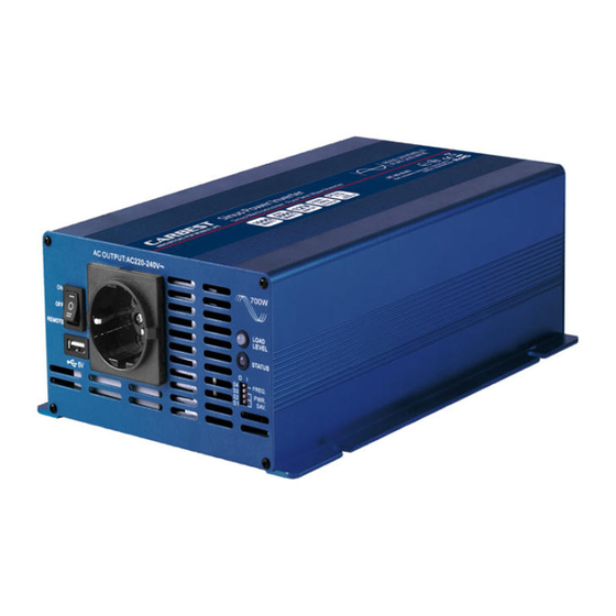
Carbest 82286 Kullanım Kılavuzu - Sayfa 10
İnvertör Carbest 82286 için çevrimiçi göz atın veya pdf Kullanım Kılavuzu indirin. Carbest 82286 13 sayfaları. Pure sine-wave inverter
Ayrıca Carbest 82286 için: Kullanım Kılavuzu (20 sayfalar)

Notes:
• Before installing the inverter, make sure the main switch must be "OFF".
• Before using the remote unit, make sure the main switch must be "Remote".
• Ensure the remote control contact is off.
5-5.DC input terminals:
Connect to 12V battery or the other power sources. (+) is positive, (-) is negative. Reverse polarity connection will blow
internal fuse and may damage inverter permanently
Model
12V
5-6. Protection features
Model
Shutdown
12V
16V
Note: the specifications are subject to change without notice.
6.
MAKING DC WIRING CONNECTIONS
Follow this procedure to connect the battery cables to the DC input terminals of the inverter. Your cable should be as
short as possible enough to handle the required current in accordance with the electrical codes or regulations applica-
tion. Cables without an adequate gauge ( too narrow or too long ) will decrease the inverter performances such as poor
surge capability and low input voltage warnings frequently and shutdowns. UVP warning presents due to DC voltage
drop across the cables from the inverter to the batteries.
The longer or narrower the cables, the greater the voltage drop.
Increasing your DC cable size will help improve the situation.
Warning The installation of a fuse must be on positive cable. Failure to place a fuse on "+" cables
running between the inverter and battery may cause damage to the inverter and will void warranty.
7.
INVERTER OPERATION
To operate the power inverter, turn the main switch ON, the power inverter is now ready to deliver AC power to your
loads. If there is several loads use, turn them on separately after the inverter has been "ON" in order to prevent the
OVP present caused by the surge power.
• Set the power switch to the "ON" position and the buzzer will send out "Beep" sounds at the moment the inverter
will do self-diagnosis, then the power status LED indicators will also appear various colors, finally the buzzer will
sound another" Beep" and the power status LED indicators will turn to" green" color, the inverter starts working
successfully.
• Set the power switch to the OFF position, the inverter stops and all the lights that are on, will go off.
• Set power inverter switch to the ON position and turn the test load on. The inverter should supply power to the
load.
8.
TROUBLE SHOOTING
Warning Do not open or disassemble the inverter. Attempting to service the unit yourself may result in a risk of electri-
cal shock or fire.
10
DC input (VDC)
Over voltage
Under voltage
Restart
13V
DC input voltage
Minimum
10,5
Under voltage
alarm
Shutdown
11V
<10,5V
Maximum
15V
Over temperature protection
Shutdown
Restart
12,5V
55 °C
Restart
45 °C
