AMS AS5601 Kullanım Kılavuzu - Sayfa 3
Kontrol Ünitesi AMS AS5601 için çevrimiçi göz atın veya pdf Kullanım Kılavuzu indirin. AMS AS5601 12 sayfaları. Usb interface & programming box
Ayrıca AMS AS5601 için: Kullanıcı Kılavuzu (13 sayfalar), Manuel (13 sayfalar)

AS5601-SO_RD_ST
Operation Manual
1
General Description
The reference design allows an easy and fast evaluation of the AS5601 rotary magnetic position
sensor in the lab. Additionally it is possible to replace an existing contactless rotary knob with the
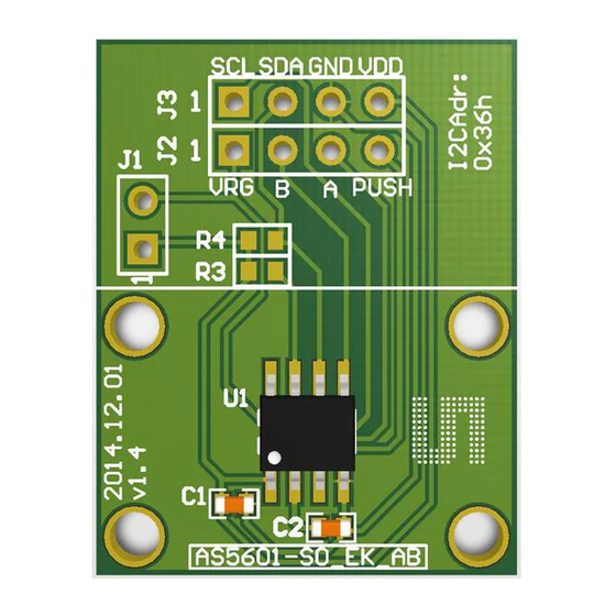
AS5601-SO_RD_ST. The module is fully assembled with and pcb including the AS5601 position
sensor and its necessary external components. All relevant signals are available on a 7-way
connector and can be easily wired to an existing application.
The AS5601 is an easy-to-program magnetic rotary position sensor with incremental quadrature
(A/B) and 12-bit digital outputs. Additionally, the PUSH output indicates fast air gap changes
between the AS5601 and magnet which can be used to implement a contactless pushbutton
function in which the knob can be pressed to move the magnet toward the AS5601.
Based on planar Hall technology, this device measures the orthogonal component of the flux
density (Bz) from an external magnet while rejecting stray magnetic fields.
The I²C interface is used for configuration and user programming of non-volatile parameters in the
AS5601 without requiring a dedicated programmer.
1.1 Kit Content
This kit contains following material listed in
webpage.
Table 1:
Kit Content
No.
Item
1
AS5601-SO_RD_ST
2
Quick Start Guide
2
Getting Started
The AS5601 reference design is a contactless rotary knob with 16 mechanical positions and a
pushbutton detection. It can be programmed over I
Note: The AS5601 is configured for a 16 positions grid and for the modules zero position.
2.1 Adapter Board Pin-Out
The pin-out of the reference module pcb is shown in
AS5601 pins refer to the product datasheet.
www.ams.com
Table
1. Additional material can be found on our
Description
2
C.
Table
Revision 1.0 / 30.06.2014
Info
Reference Module including PCB
2. For additional information on the
page 3/11
