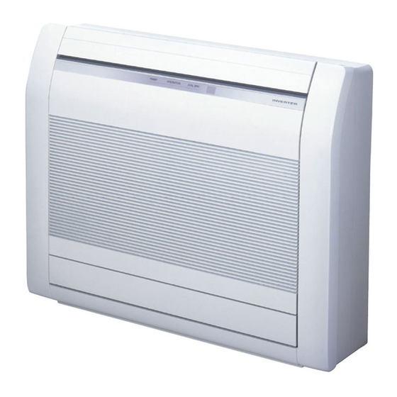
AirStage ABUA24TLAV Kurulum Kılavuzu - Sayfa 16
Klima AirStage ABUA24TLAV için çevrimiçi göz atın veya pdf Kurulum Kılavuzu indirin. AirStage ABUA24TLAV 17 sayfaları. Indoor unit

8. MOUNT THE COVER PLATE AND THE IN-
TAKE GRILLE
] 1
8.1. Handling for the pipe take-off part
When the pipe is pulled out in the direction shown in the fi gure below, cover the take-off
part with material (putty or the like) that will block it off.
UNDER CEILING TYPE
FLOOR CONSOLE TYPE
] 1
8.2. Mount the cover plate (Right)
(1) Cut a pipe exit hole in the right plate. This is only when the pipe exits from the right
side. (This operation is not required when the protrusion is on the top or rear.)
(2) Join the cover plates (right) and mount with screws.
En-15
Top
Rear
Right
Cover plate (Right) (Accessories)
Tapping screw (M4 × 10 mm)
(Accessories)
] 1
8.3. Mount the cover plate (Left)
(1) Join the cover plates (left) and mount with screws.
Tapping screw (M4 × 10 mm)
(Accessories)
8.4. Mount the intake grille
(1) Cut the right side of the intake grille. This is only when the pipe exits from the right
side.
(2) Insert the hinges on the bottom of the intake grille into the holes in the base assembly.
Then mount the arms to the 3 areas on the top of the intake grille.
9. TEST RUN
] 1
9.1. Test run using Outdoor unit (PCB)
• Refer to the Installation Manual for the outdoor unit if the PCB for the outdoor unit is to
be used for the test run.
] 1
9.2. Test run using remote controller
• Refer to the Installation Manual for the remote controller to perform the test run using
the remote controller.
• When the air conditioner is being test run, the OPERATION and TIMER indicator lamps
fl ash slowly at the same time.
Cover plate (Left)
(Accessories)
