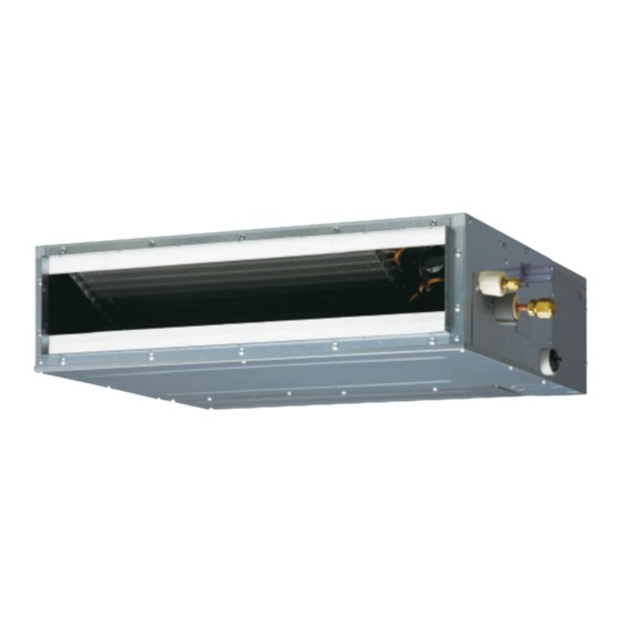
AirStage ARXD14GALH Kurulum Kılavuzu - Sayfa 16
Klima AirStage ARXD14GALH için çevrimiçi göz atın veya pdf Kurulum Kılavuzu indirin. AirStage ARXD14GALH 20 sayfaları. Indoor unit (duct type)

] 1
6.6. Remote sensor (Optional parts)
Connection method
• Connection terminals
Controller PCB
• Wiring arrangement
Controller PCB
• Remove the existing connector and replace it with the remote sensor connector (ensure
that the correct connector is used).
• The original connector should be insulated to ensure that it does not come into contact
with other electrical circuitry.
• Use conduit hole when external output cable is used.
To protect the cable insulation after opening a knockout hole, remove any burrs from
the edge of the hole.
Setting for room temperature correction
When a remote sensor is connected, set the function setting of indoor unit as indicated
below.
• Function Number "30":
Set the Setting Number to "00". (Default)
• Function Number "31":
Set the Setting Number to "02".
* Refer to "7.7. Function setting" for details about Function Number and Setting Number
] 1
6.7. IR receiver unit (Optional parts)
• For the installation method, please refer to the INSTALLATION MANUAL of IR receiver
unit.
Connection method
• Connection terminals
Controller PCB
En-15
Remote sensor
terminal (CN8)
Clamp
∗
CAUTION
IR receiver
unit terminal
(CN18)
• Wiring arrangement
Controller PCB
• Use 7 pins for receiver unit cable.
• At fi rst, connect the receiver unit cable to the controller PCB.
• Attach the core that comes between controller PCB and the clamp.
• Use conduit hole when external output cable is used.
∗
To protect the cable insulation after opening a knockout hole, remove any burrs from
the edge of the hole.
]
1
6.8. Auto louver grille (Optional parts)
Connection method
• Connection terminals
Controller PCB
• Wiring arrangement
Controller PCB
∗
To protect the cable insulation after opening a knockout hole, remove any burrs from
the edge of the hole.
Core
Clamp
CAUTION
Auto louver
grille terminal
(CN12)
Clamp
CAUTION
